This thread has been locked.
If you have a related question, please click the "Ask a related question" button in the top right corner. The newly created question will be automatically linked to this question.
Hi Team,
We are using Performance Demonstration Kit for the ADS130E08. After logging the data there are two files generated - Device_0_Codes and Device_0_Volts.
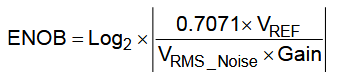
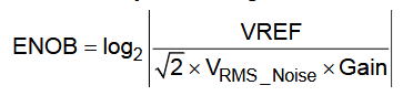
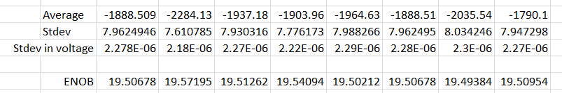
To calculate ENOB out thought is as follows,
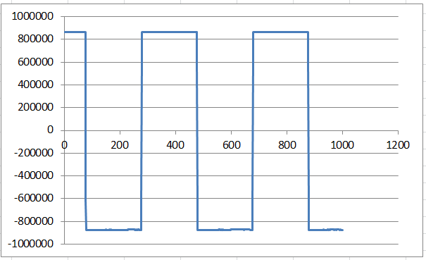
1) Open Device_0_Codes file and convert this HEX data into decimal format.
2) Take log of this so that it will give ENOB.
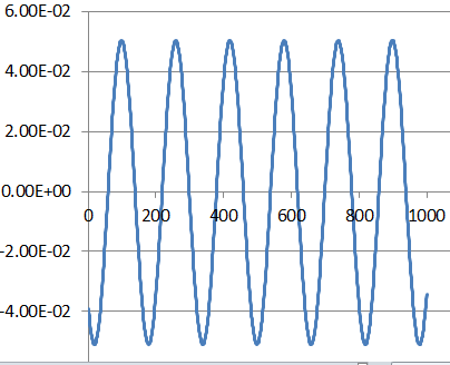
Please confirm above our understanding OR suggest what is the use of Device_0_Codes file. I am attaching both files in the post.5706.Device_0_Codes.xlsDevice_0_Volts.xls
Regards,
Yogesh
Yogesh,
ENOB is a measurement of the noise in the measurement as a comparison agains the full scale range of the device. You can see the equation for ENOB in equation 1 the datasheet:
For your measurements, you have put in an input signal that is some sort of sinusoid. There are some errors in the datafile for the raw data, but for the voltage data, you get something that looks like this after you compile it into excel:
If you try to use that data, then you have an input signal that you're using to try to calculate the noise.
Normally, when you want to look at ENOB, you only look at the noise. In that case, you would take the ADC inputs and short them to a mid-supply voltage and you're looking at the noise in the measurement (which would be near 0V after you remove the offset). After you collect the noise data, then you would calculate the RMS value and plug it into the first equation.
Joseph Wu
Hi Joseph,
Thanks for reply,
But did you reffer my Data_code_Xls file.
There are few queries,
1) What is the use of Data_code file?
2) Can we calculate ENOB using Data_code file?
There are some equations available in goggle and we apply them in Data_code file and we found some ENOB values also.
Please guide me,
Regards,
Yogesh
0844.Device_0_Codes.xls5518.Device_0_Volts.xlsDevice_0_Analysis.xlsPlease find other data file for your reference.
We have 2 different ADC_EVM softwares , 1) ADS130 and 2) ADS131.
When I capture data from ADS130 I will get ENOB values less than 16 bit and When I calculate ENOB values from ADS131 I will get ENOB values 18 bit.
Please reff file from ADs131 in the attachment,
I am using Data_codes excel files.
Process we follow is ,
1) Data_code file content HEX data
2) Conver HEX into DEC
3) Take Log with base 2
4) Get ENOB
Please confirm this
Regards,
Yogesh
Yogesh,
As I mentioned in the previous post, this is a measure of the noise in comparison to the full scale range of the input. Because of this, you don't want to measure the ENOB with a signal (unless you can completely remove the signal from the measurement.
When I opened your file of data, I made the conversion to codes and got this:
I'm not sure where the square wave comes from, but you won't be able to extract the noise from it, unless you choose a stable input. You might be able to do this if you only look at points that aren't changing (with a square wave, you may be able to do this but in this case, I'm not sure if your signal has it's own noise contribution.
Here, I took and ADS131E08EVM and made some of my own measurements with the inputs shorted, using 1kSPS as the data rate. I compiled this into an excel file here:
Device_1000_Codes.xlsx
Taking the data, I calculate the standard deviation of noise, which becomes the rms noise value. Then I calculate the ENOB from the equation shown in the datasheet:
This gives me the result for the 8 channels:
and I can compare this with the noise from the datasheet in table 1.
In the end, the values are not too far apart. I'm using different supplies, but I'm using the 2.4V internal reference.
Regardless, this was the process I used to calculate the ENOB. I would say there may be different ways to calculate ENOB based on the rms of the noise. In many cases, calculations will use the peak-to-peak noise and in others some will use a different scaling of the rms noise.
Joseph Wu
Texas_ADC_input_short.pptx
Hi Joseph,
Thanks for giving detail information.
We are planning to do the same method suggested by you. Before doing any measurement I want to reconfirm our connections.
Please find presentation file attached. Our query is I am shorting ADC inputs but as per your earlier post you told that reference voltage should connected to ADC shorted input.
So from where we can get that point on EVM board.
Regards,
Yogesh
Excellent help Joseph....
I will try as per your suggestion and , will update you accordingly.
Regards,
Yogesh
Hi Joseph,
Thanks for prompt reply,
You are correct, TP12 is ground.
My query is different.
What I am asking to you is , did u inject +/- 2.5 VDC externally to all ADC inputs?
OR
With out any input you just take measurements.
Regards,
Yogesh
Hi Joseph,
Thanks for reply,
As per your reply it and my understanding it seems that you are connecting all shorted inputs to midsupply. So 2.4 VDC will inject in ADC input.
Please confirm,
Regards,
Yogesh