This thread has been locked.

If you have a related question, please click the "Ask a related question" button in the top right corner. The newly created question will be automatically linked to this question.

ADC128D818: The failed IN0-IN7 reading issue by using ADC128D818CIMTX/NOPB due to Reg 0CH being 01(busy) always

Part Number: ADC128D818

Dear expert:

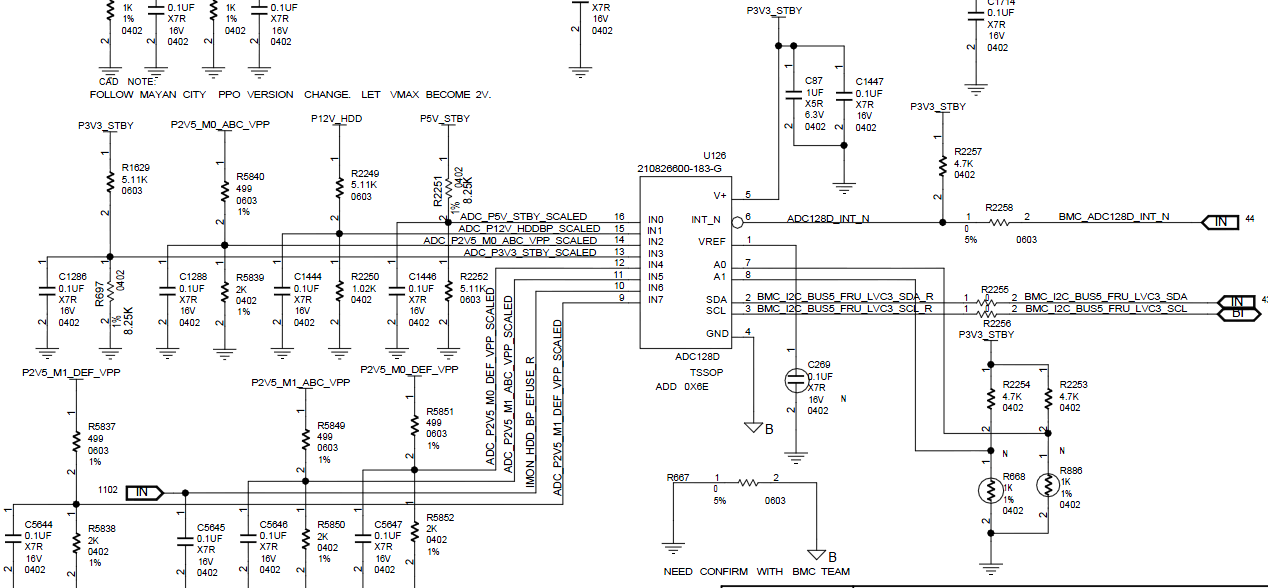
     I have an urgent issue on this application from customer side and need your help to resolve. the issue is:  9 boards of 113 boards have the failed IN0-IN7 reading problem, the failed board is observed by the 01 reading from Reg 0CH, However , the normal one is with the 00 reading from Reg 0C. the circuit is attached here.

the configuration setting is :

 1: BMC configure 00H and 0BH as 01 and 02, 07H is with default setting.

 2: BMC will read the value of 20H-27H per 30s.

 3, BMC will read the value of 20H-27H per 10s,

 4, repeat the process of 2 and 3.

When issue happen, all voltage attached to this chip can not be read by BMC, but the other sensor reading of BMC is normal.We tried to reboot the system and reset BMC, issue still exist. The only way to recover is AC power off and on, which means that reset the ADC can make it work normal.

I2C signal between BMC and ADC128D is good. This issue have no relationship with signal integrated.

We compared the failure unit register value with good unit, the register address 01h and 0ch are different.


Failure unit register value is:

register 01h = 00

register 0ch = 01


Good unit register value is:

register 01h = ff

register 0ch = 00

They are read only register,

So could you help to check if there is any problem, so what condition has caused the ADC is still busy all the way under this condition,  then how to close this issue?

thanks very much!

  • Hi team:

         There is another supplement for this issue : this fault occurs when the power cycle experiment, for example, sometime, the fault can occur for the fifth time and been kept forever, which means the IN0-IN7 cannot be read due to the busy indication of 0Ch Reg forever, but the fault can be resolved through powering off and powering on again.,

    Another working condition I need to point out is : when powering on, the Vcc of ADC128 (P3V3_STBY) is established later than IN0(P5V_STBY) , I do not know if this has some effect on the failure.

    thanks!

  • Richard,


    I'm sorry I missed the first post. I'll need a little time to look into this and I'll try to get back to you over the weekend.


    Joseph Wu
  • Richard,


    I've read your post and I've looked through your schematic, but don't see anything that might be a problem. However, I do have some comments and questions.

    When the Not Ready bit comes up as 1 in the Busy Status Register, has the customer checked what happens when they add extra time? In the Quick Start section on page 33 of the datasheet, it does mention giving extra time, before proceeding (even if there is a 33ms wait after power up). I would start by adding in increments of 50ms to see if the device responds after the power-on reset.

    Does this error only occur in power cycling experiment? How fast is the power supply being cycled? Are they able to experiment with different time periods of cycling power? You mentioned that there might be power applied to the inputs before the power is applied to the ADC. It looks like all of the inputs are nominally about 2V input. Are all of these inputs coming up before the power supply?

    I've seen in other devices that the digital section may have problems if the device does not go through a proper power-on reset and the device experiences a brown-out condition, where the supply dips below the normal operating condition, but does not trigger the power-on reset when the power supply returns to normal. In such cases, the device should be completely powered down before the supply power is returned to normal. To do this they should ensure that inputs are unpowered so they cannot source current into the device. Also, they may need to reduce bypass capacitance to remove charge from the supplies so that the supply voltage drops faster to below the POR level.

    I've checked through the E2E forums, and I haven't found any cases of the ADC128D818 having problems with the busy status register or any issues with the power cycling of this device. I would start with adding extra time to see if the Busy Status Register clears up. After that, I would start by shorting the inputs, to see the error clears up without the input voltages supplying extra current to keep the device in a brown out condition. Last, I'd check to see if removing the bypass capacitance helps with the repeated cycling.

    How are the power cycling tests being run? Do you have information about the power cycling times, the ramp rates, and duration of the on and off times used?


    Joseph Wu