This thread has been locked.

If you have a related question, please click the "Ask a related question" button in the top right corner. The newly created question will be automatically linked to this question.

ADS1675: SYNCHRONIZING MULTIPLE ADS1675s

Part Number: ADS1675
Other Parts Discussed in Thread: SN74AUC1G74

Hello,

I am debugging a DAQ-system consisting of four ADS1675 that are expected to sample and output data simultaneously but do not. I measure deviations in arrival time of DRDY of around 10 .. 100 nanoseconds. The parts are configured in High-Speed LVDS mode and running continuously at full speed 4 MSPS. Data on outputs is correct (correspond to analog input).

START is synced to falling edge of CLK and pulsed for 3 CLK cycles before being held high.

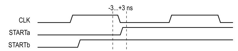
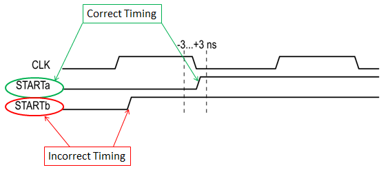
1. In the datasheet (SBAS416D) under TIMING REQUIREMENTS: High-Speed LVDS on page 7 is a setup requirement for SYMBOL tSTCLK given by -3..3 ns. How should one understand a maximum setup time?

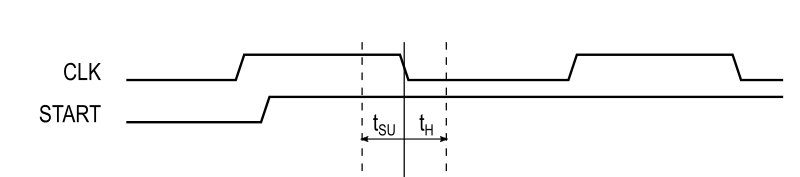
2. Under TIMING REQUIREMENTS: START on page 9 is a minimum setup time of 0.5 tCLK to rising edge given, which is in contrast to point 1.


Do you have an idea why data output is not synchronous? What is the achievable or typical deviation of DRDY output time between multiple synced ADS1675s?


Regards.

  • Hello,

    The primary support engineer for the ADS1675 is out of the office today returning tomorrow.  They will respond tomorrow or the day after.

  • Hello,

    The timing requirements on page 7 for High-Speed mode are the correct ones when operating in the high speed mode.  For low speed mode, follow the t-START-CLKR requirement of 0.5 t-CLK. 

    Since you are operating in high speed mode, ensure that the rising edge of START is within +/-3nS of the falling edge of CLK so that multiple devices synchronize to the same CLK edge.

    After synchronization, all ADS1675's should be synchronized to the same CLK edge.  There is a 13ns to 20nS delay between CLK and SCLK, and another 2nS to 3nS delay from SCLK to DRDY.  Worst case between parts, there could be a 7+1=8nS difference in delay, plus any additional delays due to CLK delays on the board.

    Since you are seeing as much as 100nS difference, it appears that the devices are not properly synchronizing to the same CLK edge.  Please make sure all ADS1675 devices share the same CLK and START signals, and issue a START pulse after the device has powered up, and the PLL has had enough time (80uS) to settle.

    Regards,
    Keith Nicholas
    Precision ADC Applications

  • Hello Mr. Nicholas,

    Thank you for the answer. Could you please explain the reason for this strict setup timing requirement for signal START? Why should START be applied not later than 12,625 ns and not earlier than 18,625 ns before rising edge of CLK? Why can’t we just synchronize START with a flip-flop (SN74auc1g74) that is placed next to the ADC using the same CLK?

    Regards.

  • Hello,

    The strict timing requirement is needed to ensure multiple ADC's are synchronized to the same CLK rising edge.  If START signal does not meet these requirements, then multiple ADC's could be off by 1 t-CLK period.

    I do not see any reason why you could not use a flip-flop to synchronize the START signal to the CLK, as long as all ADC START pins are connected to the same flip-flop output.

    Regards,
    Keith

  • Hello Keith,

    I have attached a diagram. STARTa is the version how I would interpret the datasheet demands. In my last commit from October 15th I have proposed version STARTb. Rising edge of START is 0.6 … 3.2 ns after rising edge of CLK. The setup timing requirement of the datasheet is clearly not met. Do you still see no reason using version STARTb?

    The word “strict” referred to the narrow eye of 6 ns around falling edge of CLK. This results in setup and hold times of 12 ns. Common flip-flops e.g. SN74AUC1G74 demand around 0.4 ns.

    Regards.

  • Hello,

    STARTb will not correctly synchronize the ADC's.  If you can get a fast enough flip-flop, you can clock the STARTb signal on the falling edge to get it closer to the STARTa requirement.

    Regards,
    Keith

  • Hello Keith,

    having counted the CLK cycles between rising edge of ACLK and first DRDY, which shall be 1324 according to Table 6, my colleagues and I came to the following conclusion:

    The timing requirement in datasheet tSTCLK Setup time, rising edge of START to falling edge of CLK min = –3 ns and max = 3 ns means setup time tSU of 3 ns and hold time tH of 3 ns regarding falling edge of CLK. That way proposed version STARTb would be correct and version STARTa off-limits.

    Can you confirm this?

    Regards.

  • Hello,

    Now I understand your question.

    The rising edge of start must fall inside the window, +/-3nS, around the falling edge of CLK, NOT outside this window.  In your previous drawing, STARTb is outside this window and does not meet the requirements in Figure 2 of the datasheet. 

    The STARTa signal is inside this window, and does meet the timing requirements as shown in Figure 2.

    Regards,
    Keith