This thread has been locked.

If you have a related question, please click the "Ask a related question" button in the top right corner. The newly created question will be automatically linked to this question.

TLV2542: Reason for reversed output data

Guru 19565 points
Part Number: TLV2542

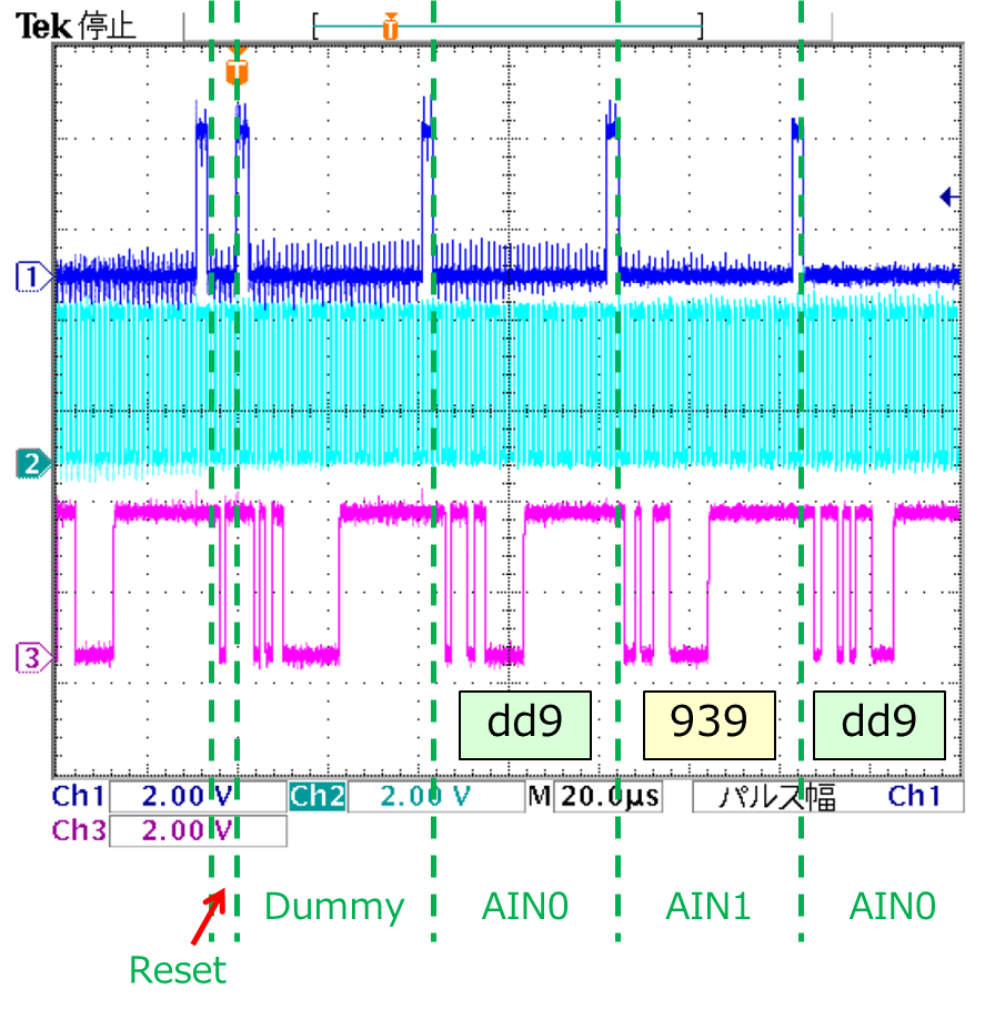
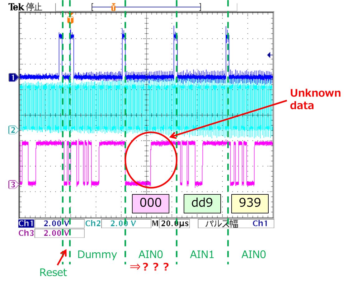
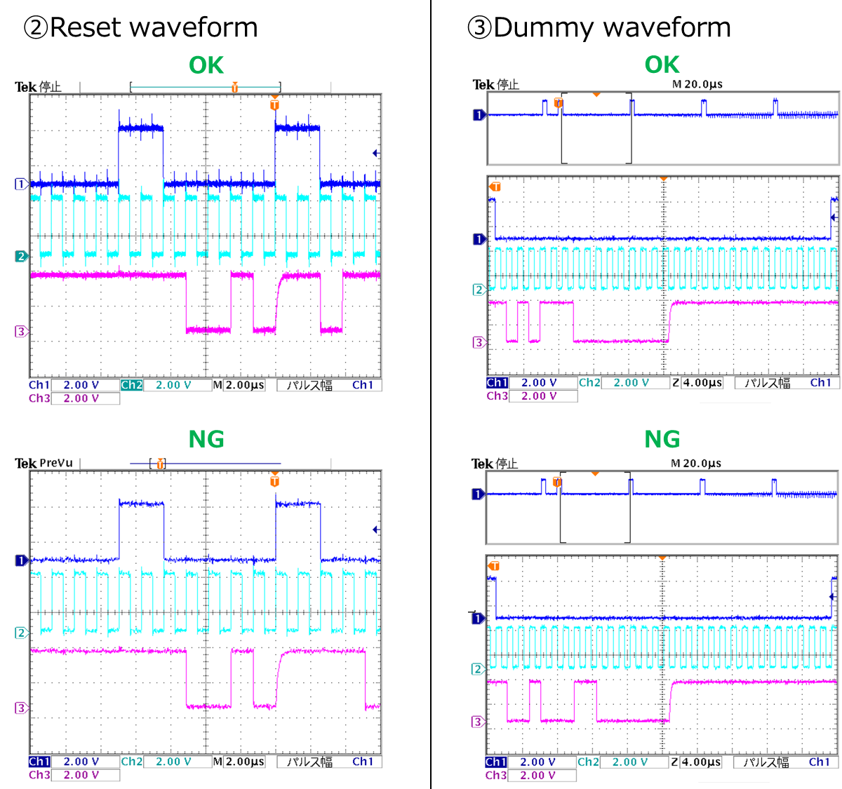
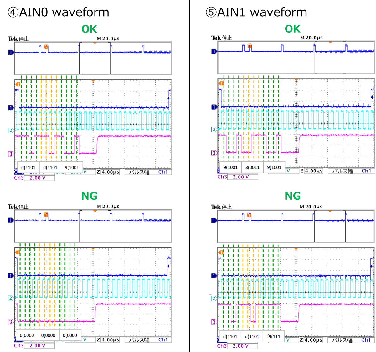
About TLV2542, certain probability occur output data error; reversed ch0 and ch1.

Please let me know about the reason and measure.

【Condition】

・This error occur 9 per 200 of TLV2542 board. 

・When 9's error TLV2542 are changed frequency below, 781.25kHz was only error.

 ⇒100KHz:OK, 500KHz:OK, 781.25KHz:NG, 1MHz:OK, 1.5152MHz:OK, 2.778MHz:OK, 5MHz:OK

 Is frequency relation for above error?

・Vdd: 3.3V, Vref; 2.5V

Best regards,

Satoshi

  • Hi Satoshi,

    I suspect the issue is cause by a short cycled /CS input.  Can you please provide screen captures at an 'OK' and 'NG' frequencies?  I'd like to see /CS, SCLK and SDO please all in one capture for one conversion cycle.

  • Tom-san

    Thank you for reply, 

    I attached waveform below, please see and any advice.

    ※ch1(Blue): /CS, ch2(Light blue): SCLK, ch3(Pink): SDO, frequency: 780kHz

    ①Overall waveform

    ・OK

    ・NG

    Best regards,

    Satoshi

  • Hi Satoshi,

    Thank you for the screen captures!  Do you always see this '0x000' (the Unknown Data) output before the channel swap?  If 0xDD9 is correct for CH0 and 0x939 is correct for CH1, it almost looks like there was an extra data set slipped in after the DUMMY cycle.  Can you also clarify for me if this is 9 of 200 boards that show this issue, or is it 9 of 200 resets?

  • Tom-san

    Thank you for reply,

    I answer your question below.

    ・Unknown data is output always "0x0000".

    ・9 of 200 mean the ratio of the board(device).

    Please let me know if there any point of notice.


    Best regards,

    Satoshi

  • Hi Satoshi,

    Do you have the ability to modify the timing between the rising SCLK and rising /CS signals?  I came across an investigation I did for another customer several years ago where they were having a similar issue when trying to synchronize the MUX from power up.  In that case, they had started with the /CS pin high before the SCLK was started.  They would get 'unknown data' followed by CH1 then CH0, essentially what you are seeing.  I am wondering if you have a similar problem here - where perhaps at certain SCLK frequencies, there is a timing dependency on rising /CS to rising SCLK.

  • Tom-san

    Thank you for reply,

    Modified waveform (/CS pin high after SCLK was started) is attached below, but data was still error.

    ※ch1(Blue): /CS, ch2(Light blue): SCLK, ch3(Pink): SDO, frequency: 780kHz

    Additional information and question is below;

    ①Is there the other reason? customer is curious about 9 of 200 board are certainly occur error.

    ②About 200 boards all, these are same error on the condition of 2.7MHz, occurred probability is about 1%.

     (9-NG board is 100% occur on 780kHz, the other frequency are not occur)

     Is there any relation of frequency?   

    ③I found the other E2E thread.

     These are described "/CS high for 3 clock was not occur", but answer is "3 clock is not effect".

     I think that 3 clock is effective, is it correct? Please let me confirm about these point.

    https://e2e.ti.com/support/data-converters/f/73/t/431609

    Best regards,

    Satoshi

  • Hi Satoshi,

    It would be an interesting experiment, if you can try 3 SCLKs high /CS and it works, do let me know.

  • Tom-san

    When tried 3SCLK high /CS, it was worked.

    Customer want to know opinion from TI for three points below;

    ①Is "3 clock" correct measure? 

     If correct, please let me know about the reason and principle for measure.

    ②Why 780kHz only 100% occurred?

    ③Why occur only 9 per 200 board? (Variation for TLV2542 spec?)

    Best regards,

    Satoshi

  • Hi Satoshi!

    Great news!  I am happy to hear that it's working but I'll have to chat with the design crew to try and understand why.  One of the questions they will ask me is "Why are you using multiple SCLK frequencies?"  Given the holiday season is upon us, there is limited coverage on the forum through the end of the year and the first week of January, so I'll try to get answers for you by January 6th.

  • Tom-san

    Thank you for feedback to design crew,

    I looking forward your answer.

    Best regards,

    Satoshi

  • Hi Satoshi,

    I sent another note today.  Can you tell me why you are using so many different clock frequencies?

  • Tom-san

    Thank you for reply,

    Customer's requested clock frequency is only 781.25kHz.

    The reason for checked the other clock frequencies are investigation of cause of problem.

    I guess that one of possibility to cause is depend on clock frequency.

    Best regards,

    Satoshi

  • Hi Satoshi,

    Will the three cycles of SCLK be an acceptable solution for you?

  • Tom-san

    Yes, we will accept three cycles of SCLK if clear the reason of reversed output data and relation for depend on clock frequency.

    Best regards,

    Satoshi

  • Hi Satoshi,

    I'm still trying to get an answer on this issue.  Do you have one or two of the 9 subject parts you can pass to one of my local associates to take a look at in the lab?

  • Tom-san

    Thank you for examination.

    Customer is confirming about whether or not for pass the IC to you. (I think probably to difficult)

    I will report to you if there any update.

    Best regards,

    Satoshi

  • Tom-san

    Please let me confirm just in case.

    Is parts mean simple substance of TLV2542, is it correct?

    Or, do you need TLV2542 with customer's board? 

    And, how long do you need to borrow?

    Best regards,

    Satoshi

  • Hi Satoshi,

    Just TLV2542 parts that show the issue.

  • Tom-san

    We should report complicated detail about TLV2542.

    May I tell me your e-mail address?

    Or, please send to below e-mail address.

    kawabata.s at teldevice.co.jp

    Best regards,

    Satoshi