This thread has been locked.

If you have a related question, please click the "Ask a related question" button in the top right corner. The newly created question will be automatically linked to this question.

ADS1263EVM-PDK: Accelerometer Sampling Connection

Part Number: ADS1263EVM-PDK
Other Parts Discussed in Thread: ADS1263

Dear All,

In my group, we are trying to sample an accelerometer signal comes from ADXL354 sensor. The sensor application circuit is shown here

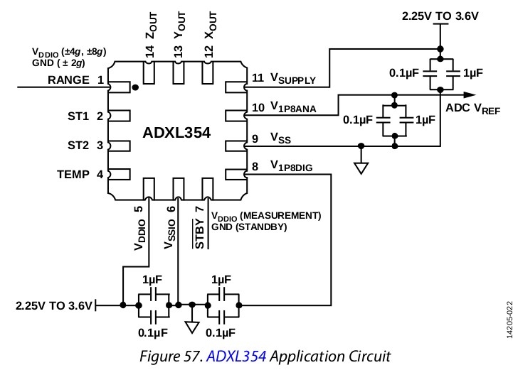
As shown in the user guide (P22) , The V1P8ANA pin (no 10 in the application circuit) should be used as a reference voltage in the ADC (I connected it to AIN0 as a REFP). And I connected VSS to AIN1 as a REFN.

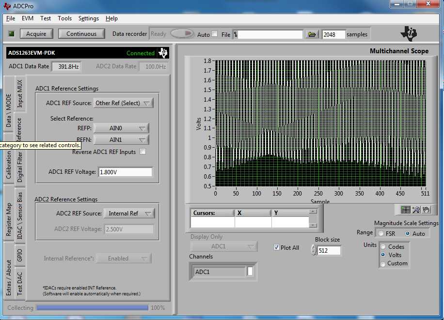
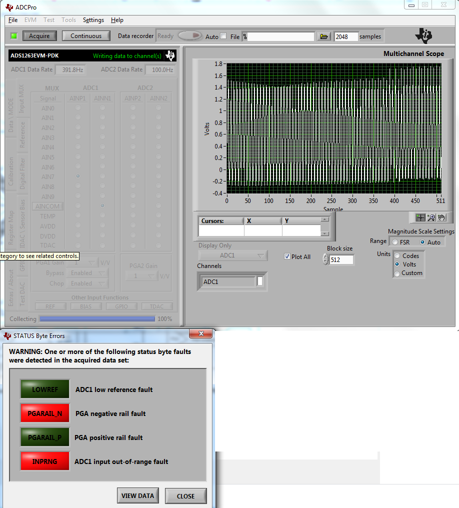
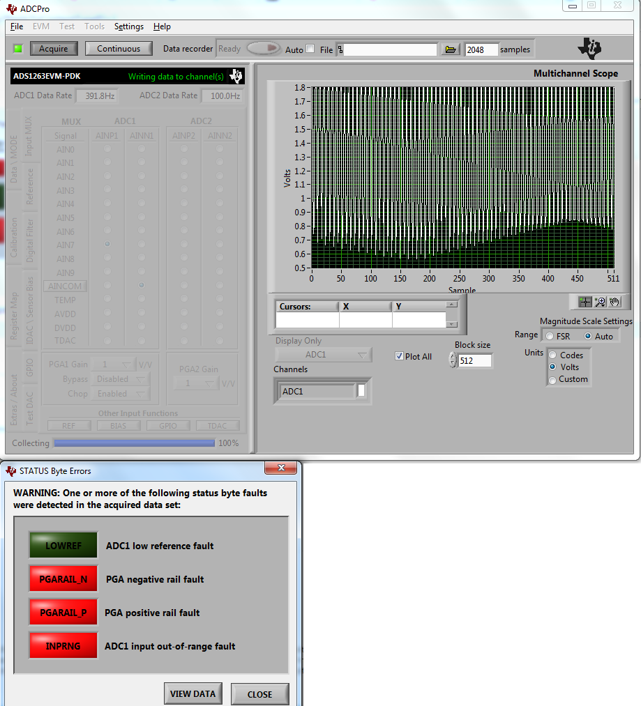
Then, I connected the ZOUT signal (single ended signal) to AIN7. I am using a wall adapter to excite the ADC (5V and ground). When I try to sample the signal, I got the all 4 errors (marked with red) appears. When I made the AINN1 to be AINCOM. I got only three errors as shown in the attached photo.

When I press ANICOM, all of them disappears and I got some signal but I am not sure if it is correct what I connected so far because the amplitude of the measured voltage is important to determine the amount of gravity it experiences.

  • Hi Mohamed,

    ADS1263 converts the signal between two analog inputs, when your ZOUT signal is connected to AIN7 as positive input, you need another input pin (for example AIN8) as negative input of ADC. You need to configure the INPMUX register to select AIN7 as positive input and AIN8 as negative input for internal multiplexer.

    Also, since your ZOUT signal is single-ended signal, you need to connect the input signals and configure the ADC properly by enabling internal PGA or bypassing it. Please see the connection recommendations for signal-ended input below:

    Best regards,

    Dale 

  • Hi Dale, 

    Thanks for your reply. I tried the PGA bypass option first and it does not work either. It shows the errors appears in the following picture. 

    I don't know if something else is wrong here. Then, I tried the bipolar option. The same 3 errors appeared again like following: 

    The last option is being done by clicking on the UNICOM icon and this is the only working condition. Do you have any idea why the PGA still showing some errors however it is bypassed?  

  • Hi Mohamed,

    Can you please provide detailed information about your test? for example, for PGA bypass experiment, your signal is supposed to be connected to the AIN7, did you have any connection on AINCOM in your test? also, can you please use a precision signal source instead of sensor ADXL354 output as an input signal to the ADC for the est?

    Best regards,

    Dale