This thread has been locked.

If you have a related question, please click the "Ask a related question" button in the top right corner. The newly created question will be automatically linked to this question.

ADS8332: Pseudocode to guide on basic reading

Part Number: ADS8332

I'm trying to talk to a single ADS8332 over 16 bit SPI, the host is a Cortex M4. I'm using internal CCLK and manual channel select & trigger, monitoring EOC.

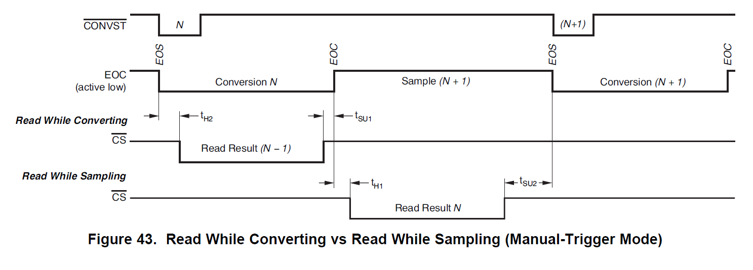
I can't understand from the datasheet, the correct sequence to read the conversion result from channel N.

Is there any useful guidance, pseudocode example, waveform traces, to show how this should be done?

  • Hello,

    Unfortunately there is no sample code available.

    I suggest using an oscilloscope probed at the digital communications pins to visually check if what you are expecting from the bus is in fact actually what is happening. This will provide a visual check and easy timing requirement check. this then can be compared to the timing diagrams in the datasheet.

    Also, use known DC inputs to compare output with expected output ex Ch0 = gnd, Ch1=1V and so on

    Please provide scope shot once available to debug.

    Regards

    Cynthia

  • Waveforms, that's just SPI configuration, not a problem. Known voltages on ADC inputs, yes, I'd thought of that.

    It is the command sequence that is undocumented.

    To set a configuration word 0x*67D, I should send 0xE67D?

    To read the configuration register, I should send 0xC000 0x0000, the CFR value being returned during the last 16 clocks?

    What sequence to select input #3, and read back the ADC result? 0x3000, 0xD000, 0x0000?

    A couple of simple interface diagrams, or some example code, would be really helpful. The datasheet plots don't cover these aspects.

  • It seems the mux is changing on the nCONV edge, makes me think it is automatically incrementing the input channel, and that my configuration word didn't get set. There must be some guidance on these basics, or do I have to deduce it myself? Does every user have to figure this out from scratch?

  • OK, progress. Some changes to the SPI config & instructions, I can now write a sensible config register and read it back repeatedly.

    I'm still not clear on the correct sequence of instructions to set channel N, and after conversion, read the result.

  • Alex,

    Glad you are making progress.

    The device can work in manual mode or in auto channel mode. the default is in auto channel mode, where channel will be sampled in sequential order.

    I suggest using the EOC pin as an indicator for when as for when to read out results. Figure 43 through 45 will help with this.

    As for communicating with the device. The complete serial I/O cycle starts after the falling edge of FS/CS and ends 16 falling edges of SCLK later. The serial interface works with CPOL = 1, CPHA = 0. This setting means the falling edge of FS/CS may fall while SCLK is high. The same timing relaxation applies to the rising edge of FS/CS where SCLK may be high or low as long as the last SCLK falling edge happens before the rising edge of FS/CS.

    Table 4 of the datasheet defines the command registers.  Here is where you can select the next channel in manual mode. This is also where you can read or write to the configuration register

    Table 5 in the datasheet provides the configuration map. I would suggest using the default until you are able to communicate as desired, then change to your applications needs. 

    Section 9 on the datasheet explains how to write and read to the converter registers. To read conversion data, depending on what clock mode (default internal) you need to provide enough SCLKs to output the data.

    Regards

    Cynthia

  • Cynthia, thanks, but all of this is in the datasheet. What is omitted is the command sequence.

    I've figured it out and it is in fact  very simple. All it needs is one paragraph in the datasheet to save designers lots of heartache & anxiety.

    The serial data out pin can report either the contents of the config register (READ CFR) or the last conversion result (READ CDR)

    Once you've issued the READ CDR command, and assuming you are manually selecting channels and using "EOC" to detect a complete conversion, it is a simple as:

    select channel N

    pulse CONVST, wait for EOC

    select channel N+1, in the process receiving the result of the channel N conversion

    pulse CONVST, wait for EOC

    select channel N+2 etc....

    16 clocks to select next channel and receive the return data (assuming no "Tag" bits)

  • I was a little premature in this statement, I thought I understood operations but tests suggest it is slightly more complex.

    This works:

    send "Select channel N"

    <conversion cycle>

    send "Read data" command - ADC data on SDO

    send "Select channel N+1" - same ADC data again on SDO

    <conversion cycle>

    send "Read data" command - ADC data on SDO

    send "Select channel N+2" - same ADC data again on SDO

    <conversion cycle>....

    I thought I could omit the "Read data" command from each cycle, but this didn't work.

  • Glad you were able to figure it out

    I will make note of your feedback

    Regards

    Cynthia