Other Parts Discussed in Thread: DRV8837, OPA2210, UCC27524, , ADS1261
Hello,
We are thinking about using the ADS1235 as new standard IC for load cell measurements.
I have some questions regarding AC-excitation and Ref-voltages. There is one dedicated reference input pair as well as the possibility to use AIn0 and AIn1 for reference input. The dedicated reference input pins will be used for the excitation voltage (5V). For low signal load sensors (~1mV/V) and low SPS this reference might be too high to get the full (noise free) resolution. We therefore would like to use a reduced bridge voltage as reference voltage (5V --> 1V via resistor divider) at AIn0/AIn1 and multiplex it when neccessary.
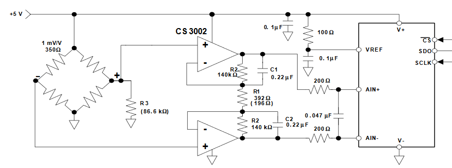
- In figure 84 from the datasheet (attached), a typical connection is shown. I would copy that filter for AIn0/AIn1, but I am not sure where to place the resistor divider. Is it better to use position 1 or position 2? I am also not quite sure about the 100kOhm resistor which connects both reference inputs. I would guess it is for the input currents if the bridge is not connected. I am also not quite sure about the values. Would I need 400-200-400 Ohms or is it possible to use higher values?
- Is it possible to use the "4-WIRE MODE (CHOP[1:0] = 11)" and connect only the ACX1 and ACX2 signals on AIn2 and AIn3 via GPIO_DIR and GPIO_CON registers? I then would use a motor driver like DRV8837 to reverse the voltage at the bridge.
- I think I got from figure 82 the information that with ACX1 high (and ACX2 low) the reference voltage is expected non-reversed (higher voltage at REFP than REFN) and vice versa (in AC-excitation mode). Is that right or does it pick automatically the the correct polarity?
- To save current, I would like to disable current consumption from the bridge. For this, I would disable the AC-mode and drive both pins low, which leaves the output of the motor driver floating. Since the reference inputs are then connected to floating inputs, is there any problem with that (besides the fact that I cannot measure)?
The favored connection would then be:
REFP0 -> positive output of bridge driver
REFN0 -> negative output of bridge driver
AIn0 -> as REFP1 -> divided positive output of bridge driver
AIn1 -> as REF3n1 -> divided negative output of bridge driver
AIn2 -> as GPIO -> ACX1
AIn3 -> as GPIO -> ACX2
AIn4 -> as analog input -> InP
AIn5 -> as analog input -> InN
Thanks in advance, Gerald