This thread has been locked.

If you have a related question, please click the "Ask a related question" button in the top right corner. The newly created question will be automatically linked to this question.

ADS8321: ADS8321 Interface problem: Cannot get ADS8321 working

Part Number: ADS8321
Other Parts Discussed in Thread: REF6025

Dear TI support team,

I am trying to interface ADS8321 16 bit ADC from TI with Teensy 3.5 (Arduino compatible platform MCU). (Vin- = 2.5V, Vref=2.5V and Vin+ is voltage input).

The ADC is supplied with 5V, while Teensy is at 3.3V. I checked the datasheet and İnput high and low levels are ok with teensy logic levels. Also, teensy input are ok with ADC output. I have made the communication as stated in the datasheet. The problem is I cannot get stable results. For example, when I am trying to read 3.3V level with ADC, it shows different and wrong values. The value I get from ADC is not same, although the einput voltage (for example 3.3V) is always same. The ADC is on PCB and Teensy is also on same pcb, they are connected with PCB track. I checked the wiring it was also correct.

I am not using SPI in the code. I am just making bit banging. For SPI part I donot know how to implement SPI by looking at device datasheet. If possible could you please provide some pseudo code for SPI  communication (what to send via SPI etc). 

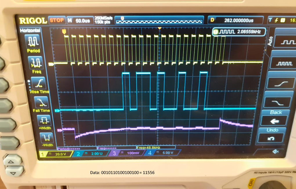
I am attaching my code and wiring diagram. Could you please help me to solve the issue?

Thank you for your help.

Ahmet

//ADS8321 current measurement, ADC 16 bit
const int clock_pin = 3;
const int data_pin = 4;
const int cs_pin = 5;

void setup () {
  pinMode(clock_pin, OUTPUT);
  pinMode(data_pin, INPUT);
  pinMode(cs_pin, OUTPUT);
}

void loop() {
  float m = readADC();
  Serial.println(m);
  delay(1000);
}


float readADC() {
  int16_t adcvalue = 0;
  digitalWrite(cs_pin, LOW);           //Select ADC

  for (int i = 0; i < 6; i++) {
    digitalWrite(clock_pin, HIGH);      // 6 clock cycles for sampling
    //delayMicroseconds(5);
    digitalWrite(clock_pin, LOW);
    //delayMicroseconds(5);
  }

  //read bits from adc, //16 clock for data reading
  for (int i = 16; i > 0; i--) { // 16 for reading
    //cycle clock
    digitalWrite(clock_pin, HIGH); // make clock high
    adcvalue |= digitalRead(data_pin) << i; // Read data bit
    digitalWrite(clock_pin, LOW); // make clock low
  }
  float a;
  a=(adcvalue+32768)*5/65536; // convert to 0-5V range

  digitalWrite(cs_pin,HIGH);          //turn off device
  return a;
}

  • Hello Ahmet,

    Are the results within 1% of expected value (a lot of noise), or are they completely incorrect?

    Would it be possible to capture DCLOCK, DOUT, and /CS with a logic analyzer or scope?  This will help confirm if you are meeting all timing requirements.

    Here are a few things to consider:

    1.  The minimum DCLOCK is 24kHz, any slower, and the converter will not provide correct results.

    2.  Your code looks correct, except for adcvalue |= digitalRead(data_pin) << i; // Read data bit.  I think you may need to shift by (i-1).

    Regards,
    Keith Nicholas
    Precision ADC Applications

  • Hello Keith,

    Thank you for your reply.

    The results are different. It is not noise I guess, for example, I am reading 3.3V as 2.56V, 4V 3.2V. Every time it changes, not within 1% of the expected value.

    I have changed the shifting, but again not stable results. I have also changed the ADS8321 with different ADS8321 but again no change.

    I have oscilloscope, I will try to capture the clock, data and #CS. I am also guessing that there is some problem regarding clocking. 

    Regards,

    Ahmet

  • Hello Ahmet,

    Yes, I would agree this is not noise related.  However, if the reference is not stable, it could show up in large reading errors.  Please add an additional 10uF of capacitance to the REF pin to see if this improves or fixes the issue.

    I will take a look at your timing once you are able to provide plots.

    Thanks,
    Keith

  • Hello Keith,

    I have taken oscilloscope plots for SCLK, Data and #CS lines. The clock frequency was adjusted to 48.8kHz. (I put 10 microsecond delay to the code to get around 50kHz frequency). ADC was reading 3.3V. On the board, 2.5V reference comes from 2.5V Voltage reference IC (MCP1501, 0.1% tolerance) and it is very close to ADS8321. This reference is used only for ADS8321. No other IC shares this reference. I will add 10uF to the reference part.

    There was clamp diode (BAT54s) in the input of ADC for voltage clamping. I also removed it to see if it causes some problem, Also previous I was just touching the voltage to the input pin with cable to test. This time I soldered it, again different values. But there was improvement. This time the values were changing between around 3.4 and 3.21V (for 3.3V)

    I am sorry as pictures are large.

    I will check if decreasing sampling rate will increase the ADC reading accuracy.

    Thank you for the help,

    Regards,

    Ahmet

  • Hi Ahmet,

    I think the likely cause of your reading errors is the reference circuit.  You have it connected to both the reference and ADC negative input, both of which are switched capacitor inputs.  The reference input requires a large capacitor, as well as fast response from the reference to maintain a constant 2.5V level.

    The MCP1501 is a low power reference, and will not have very good response time.  I suggest you look at figure 5-4 and 5-5 in the MCP1501 datasheet for guidance on adding additional capacitance without causing instability.  You can also use a reference with a high speed buffer, such as REF6025, to directly drive the pin.

    Adding additional capacitance for Vref, plus slowing the ADC conversion rate, should improve your reading accuracy if this is the issue.

    For further discussion, please take a look at TI precision labs, which discusses the reference driver requirements for SAR ADC's.

    https://training.ti.com/node/1139107?context=1139107

    Regards,
    Keith

  • Hi Keith,

    Thank you for your help.

    I will design new board, where I think to use 2 REF6025 one for Vref and one for negative input to see how it will improve accuracy. I will also study the link you provided. I will design that board as something like seperate board and if that works I will use attach it to my original board.

    Thanks again for the information and help.

    Regards,

    Ahmet