This thread has been locked.

If you have a related question, please click the "Ask a related question" button in the top right corner. The newly created question will be automatically linked to this question.

CCS/ADS1292: ads1292 / drdy problem

Part Number: ADS1292

Tool/software: Code Composer Studio

Hi,

I have a problem using ads1292.

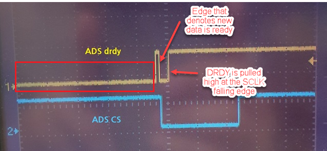
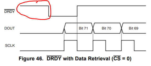
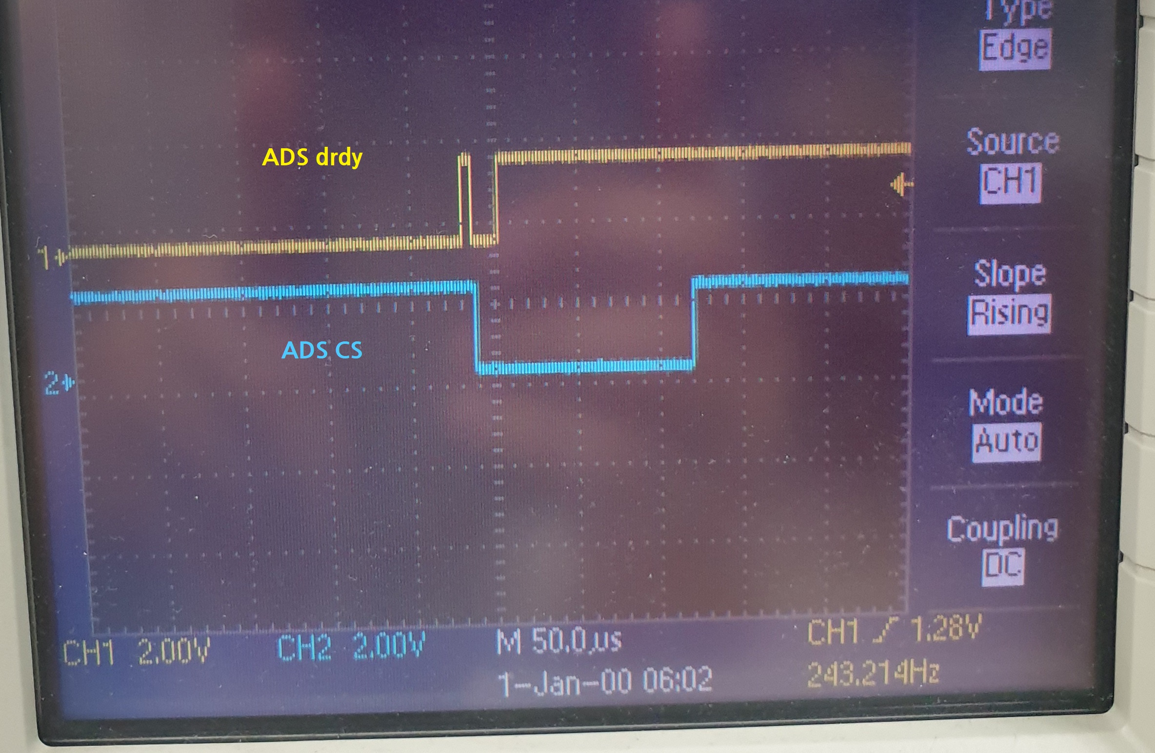
When i read sample using continuous mode, drdy pin of ads state is abnormal.

(interrupt edge is low to high : raising edge)

Does anyone know about these problem?

This is my code.

int main(void)
{

	WDT_A_hold(WDT_A_BASE);

	init_CS();
	init_GPIO();

	//GPIO_setAsPeripheralModuleFunctionOutputPin(GPIO_PORT_PJ, GPIO_PIN2 | GPIO_PIN1 | GPIO_PIN0, GPIO_PRIMARY_MODULE_FUNCTION);
	register_mainOperation(main_idle);

	__enable_interrupt();

	initUart();

	initUserPort();
	setPowerEnPin(true);

	initADS1292();
	hal_ads_start();
	read_started = 1;

	while (1)
	{
		mainOperation();

		if (ads_read_flag)
		{
			hal_ads_read_sample(ads_buff);
			ads_read_flag = 0;
		}

	}
}

#pragma vector=PORT1_VECTOR
__interrupt void P1_ISR(void)
{
	switch (__even_in_range(P1IV, P1IV_P1IFG7))
	{
	case P1IV_P1IFG1:
		ads_read_flag = 1;
		break;

	case P1IV_P1IFG2:
		afe_read_flag = 1;
		break;

	default:
		break;
	}
}

  • ADS1292 SCLK : 1MHz
  • ADS1292 CLK : 2MHz from msp430

And, this is register setting of ads1292.

		0x01,  //CONFIG1 : 4kSPS for single shot mode
		0xF3,  //CONFIG2 : enable Lead-off comparator, enable reference buffer, reference 4V
		0x10,  //LOFF
		0x65,  //Channel1 //power down
		0x65,  //Channel2 //gain12
		0x25,  //RLD_SENS
		0x0F,  //LOFF_SENS
		0x40,  //LOFF_STAT
		0x02,  //RESP1
		0x03,  //RESP2
		0x03  //GPIO

Thanks.

Regards,

Youngjun

  • Hello Youngjun,

    I do not see any issues with the DRDY signal. Please refer to section 8.5.1.6 in the ADS1292 datasheet on the description of the DRDY signal.

    DRDY will transition low when new conversion data is ready (irrespective of CS signal) and will be pulled high at the SCLK falling edge.

    In your waveform, you may also want to capture the SCLK signal for confirmation.

  • Hi Praveen,

    Thanks for replying.

    Then, is it right to read data at this point?

    The drdy interrupted twice(raising edge).

    I think drdy state of below picture have to high.

    When I read test wave data at above timing, ch2 data inverted.

    Or, data is crashed like this.

    Thanks.

    Regards,

    Youngjun

  • Hello Youngjun,

    The falling edge on DRDY denotes new data being available.

    After this falling edge, if the SCLK is not provided, then the DRDY will remain low until the next time when new data is available.

    The device will drive the line for a short duration and again pull the line low indicating the new data.

    This is the reason why the DRDY was low to begin with.

    I don't follow about the CH2 inversion. Can you provide additional details?

  • Hi Praveen,

    When i read data at first raising edge in above image, ch2 data inverted.
     

    When i read only ads data, drdy work properly.

    I think, other codes seem to interfere with the drdy timing.

    Thanks.

    Regards,

    Praveen

  • Hello Youngjun,

    You should be reading data on the falling edge of DRDY and not on the rising edge.

    Please clarify what you mean by "When i read only ads data, drdy work properly.".