This thread has been locked.

If you have a related question, please click the "Ask a related question" button in the top right corner. The newly created question will be automatically linked to this question.

ADS8588H: Oversampling plot

Part Number: ADS8588H
Other Parts Discussed in Thread: ADS8588S

HI, Gentleman:

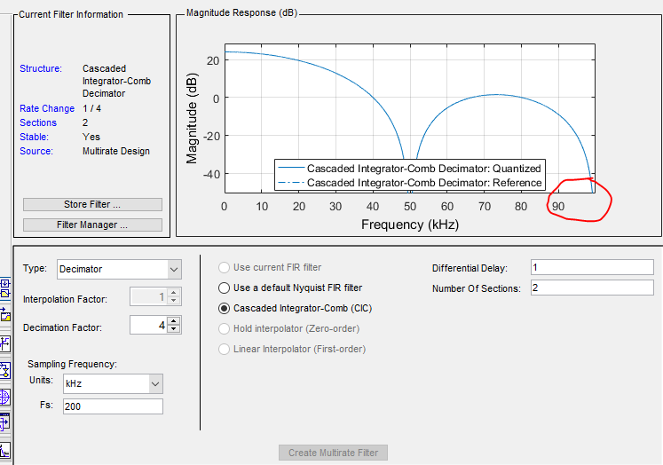
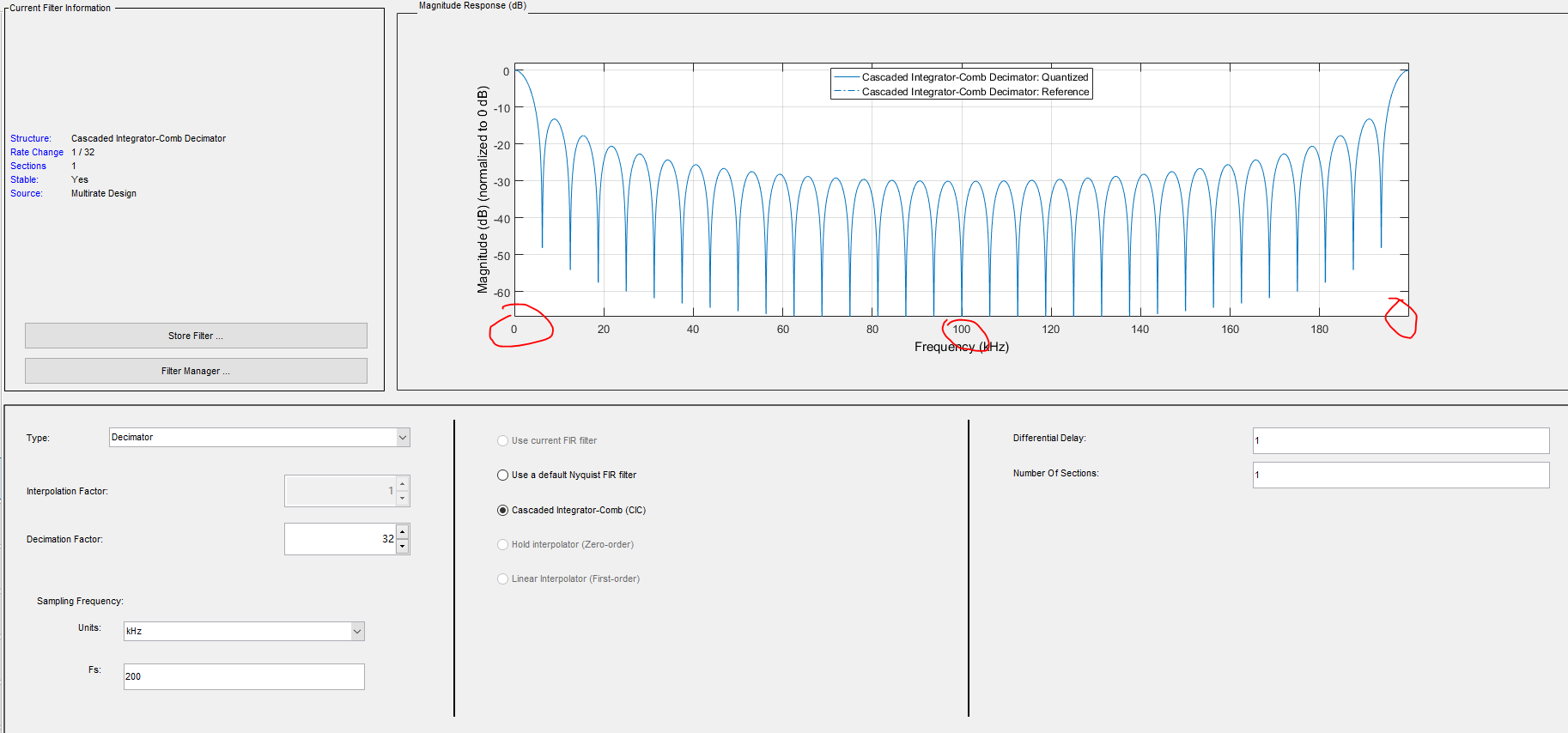
I have questions on below plot. The ADC max sampling rate in the ADS8588 is only hundreds KHz, but why the oversampling CIC filter can display like below, extend to 10MHz?

For example, If the CIC filter input is 200KHz, the frequency response is 100KHz; how to get below plot? Thanks!

  • Hello,

    Unfortunately the images you posted did not make it through.  Could you please repost the images?  Please note that the ADS8588 features an internal analog filter that limits the bandwidth between 24kHz and 16kHz depending on the settings as shown on page 8 of the datasheet.

  • Hi, Collion:

    Repost the charts. My questions is the integrated digital filter plot. Why the ADC sample rate is hundreds kHz, but the frequency response extend to 10MHz? My underding if the filter input is 200KHz, the frequency only display 100KHz. Thanks!

  • Hello,

    You will need to use the "Insert Image" buttons instead of copy/pasting the images into the text editor.  Unfortunately they did not make it through again.

  • Thanks, Collion. Do it again.

  • Thanks, Collin.

    Hello jinan,an,

    The sampling rate of the ADC is not related to the frequency you highlighted. The graph in the Figure 78 you are showing is the magnitude response for the internal digital filer on ADS8588S. The ADC is running at 200kHz (ADS8588S as an example), the actual output data rate (fd) from the ADC is 100kHz since the oversampling ratio (OSR) is 2 in the Figure 78, hence the frequency response nulls occur at f(Hz) = N* fd, where N = 1,2,3,.... you can see the exact nulls are shown at point 1(100kHz), point 2(200kHz), point 3(300kHz).. which are highlighted in the picture below. The displayed frequency region can be higher as the number is increased in integer multiples to the data rate. One application note below discusses the digital filters on Delta-Sigma ADCs, the digital filter on the ADS8588S is not exactly same as the filters discussed in the application note, however this article can give you some knowledge about the digital filter and one key function for these filters is same for decimation and oversampling.

    Digital Filter Types in Delta-Sigma ADCs

    Best regards,

    Dale

  • Thansk, Dale.

    For the decimation filter, if the filter work frequency is 200KHz, and we did the 32 decimation and the frequency response is symmetric at 100KHz, see below chart;

    While in 8588s Datasheet, the filter is monotonicity attenuation to 10MHz, not symmetric. That mean the filter work at 20MHz clock? The real decimation ratio in the chip is much higher actually than the datasheet claim ? Thanks!


  • Hello jinan,an,

    The decimation ratios are specified from 2 to 64 in the datasheet. The filter you plot is different from the filter designed on the ADS8588. If you look at the application note, you should be able to understand it. Also, there is a simple spreadsheet tool about the digital filter, you can play it,  ADS1261 Design Calculator (Rev. A) , this is a similar filter used on the ADS8588.

    Regards,

    Dale