This thread has been locked.

If you have a related question, please click the "Ask a related question" button in the top right corner. The newly created question will be automatically linked to this question.

AFE5832EVM: Data acquisition card and front-end work

Part Number: AFE5832EVM
Other Parts Discussed in Thread: AFE5832

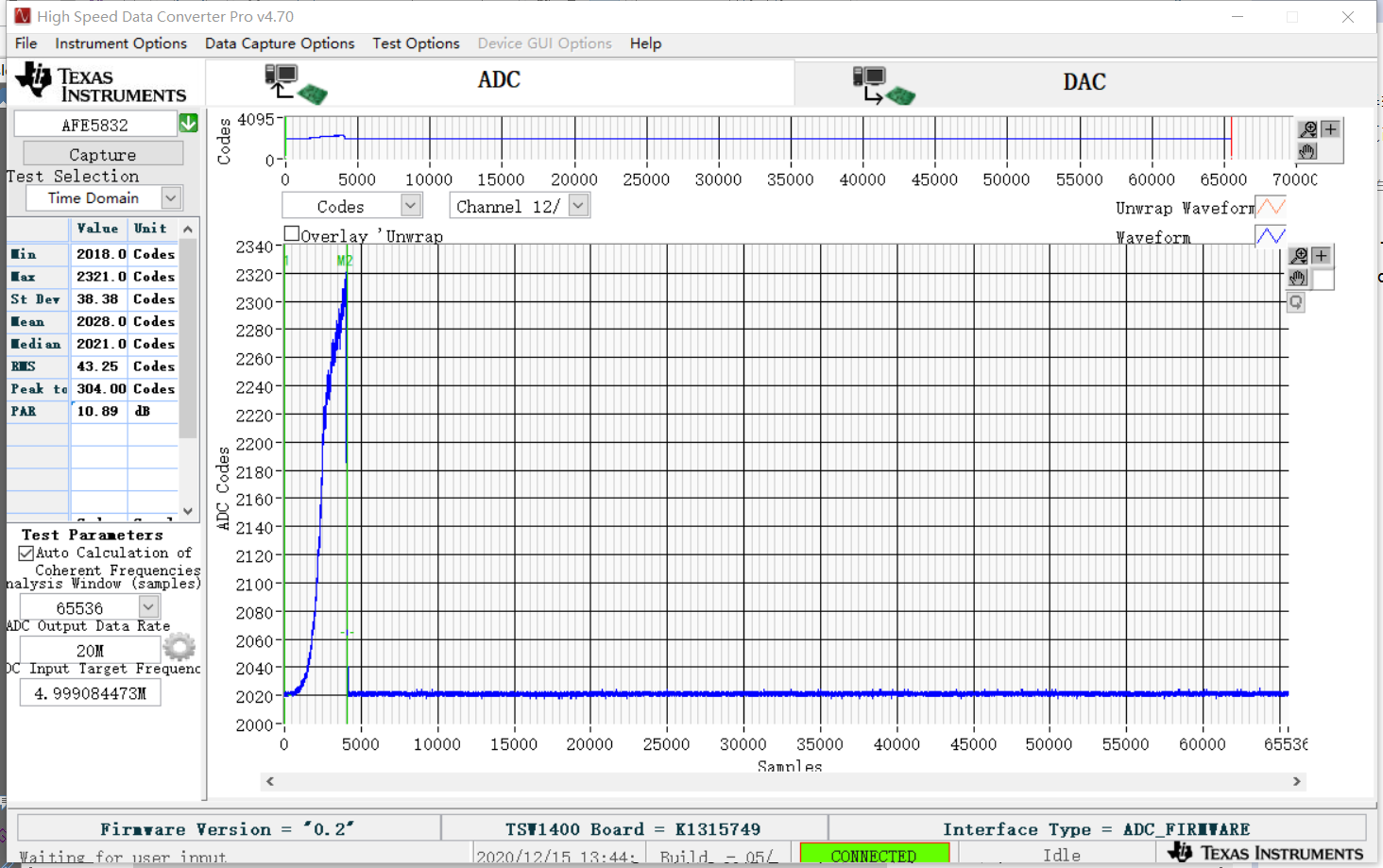
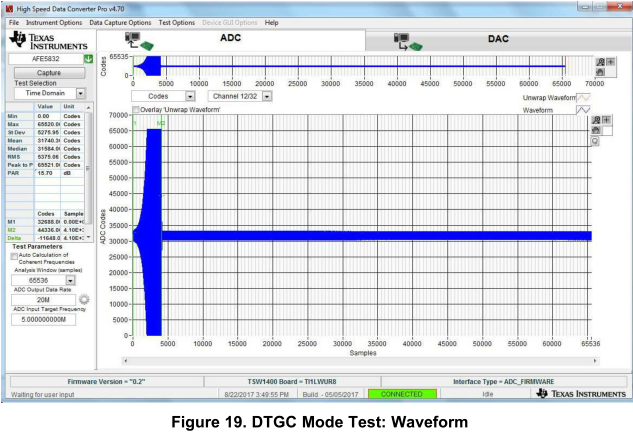
The first picture is the result of testing AFE5832EVM and TSW1400EVM, and the second picture is the manual (I use a signal generator, which can output a maximum frequency of 100Mhz. The manual says change the jumper configurations as outboard in section c.1.3 and apply a 160-MHz, 10-DBM external lmk input clock to j56 or clock at 4× the desired ADC sample rate.) what is the problem?

  • Hi,

    Thanks for using AFE5832!

    I think you need to check the input signal. look like there is no input signal is applied.  

    i would suggest you start from the  4.2 Capturing an Analog Input Signal With the LVDS Interface. first need to make sure the data can be captured with fixed gain settings. then you move to DTGC. 

    Thanks!

    Xiaochen

  • How do I determine or change the gain through the GUI?

  • You can find the information on user manual page 13:

    6. Choose the Data Formats and the Analog Configuration for each category as shown in Figure 12:

    • OUTPUT FORMAT: Select ‘LVDS: 12x 12b’

    • ADC FORMAT: Select ‘Analog Input’

    • VCA GAIN: Select ‘Mid Gain’

    • DTGC Modes: Select ‘Programmable Fixed-Gain Mode’

    Hope the user manual provides you sufficent information. 

    Thanks!

  •  I have come out with this result diagram. I input a sinusoidal signal of 5Mhz and 22mv, which is tested in DTGC according to the manual. I don't understand the relationship between the input signal and the signal displayed by this software.Or what about this DTGC?

  • I think this is the right output. please review the datasheet more. 

    22mV input the output is 2Vpp as ADC full range. the signal is saturated. So the gain is over 40dB.  our device max gain is 45dB. so it is reasonable. you can drop the signal to 5mVpp to get the exact measurement 

    you can find info from datasheet. 

    Thanks!

  • I'm inputting a continuous sinusoidal signal at 22mv, so why is it that the output is only this small?And if I look further at the output, it doesn't seem to be a regular sine wave.

  • please zoom in the waveform, then you will see the sine wave. 

    Please review the datasheet and user manual more to understand the device details. 

    our AFE is a variable gain amplifier.(VGA) our EVM is configured as variaiable gain amplifier in one operation mode, which you are using. 

    I thought you selected this AFE due to its VGA feature. Otherwise, you selected the wrong device. 

    At this moment, your EVM operates as expected. if it doesn't meet your requirement, you will need to select a different operation mode as fixed gain. or you select a different EVM. 

    Thanks! 

  • This error was encountered when using the TSW1400EVM GUI to automatically open the AFE5832 GUI. How to deal with it?

  • hi, look like you were able to use the board without problem before. what did you change to trig this error? 

    if your previous procedure works, we recommend you follow that procedure. 

    many time for windows system, restarting the windows system slove many problems:)

    Thanks!

  • I've got the result, but I don't understand what it means.ADC Output Data Rate and ADC Input Target Frequency on the left.What I understand is that the ADC Output Data rate is set to four times of the Input signal, and ADC Input Target Frequency is set to the Input signal.Why is the 7MHZ Input signal set by me and the ADC Input Target Frequency still 5MHZ,The result seems to be unchanged?In addition, what is the meaning of Sample,ADC Codes on the image interface? How can they be related to the input signals?

  • the ADC output rate is the ADC sample freq for each analog channel. Input target freq is the signal freq. Typically these two parameters are set by users.  our GUI doesn't know your input conditions.  if your signal is 7MHz, then you set as 7MHz. 

    So far, the EVM and GUI performs as it should be. I think you can find more info from the GUI user manual and device datasheet. This way, you can evaluate whether the device  or EVM can fit your needs. 

    Thanks!