


Part Number: ADS8681
Hello, There !
In one of the my project, I am trying to communicate ADS8681 with Arduino Mega-2560 using SPI Mode. On oscilloscope, getting the correct waveform across SPI pins of Arduino, but when trying to read (+- 10V) Analog data range and it shows correct 16-bit variation on variable input at display module (LCD). But Whenever removed the input (No Load at Transducer) it gives random values instead of "0". I would be grateful for any advice how to receive suitable data.
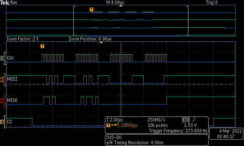
Following picture shows corresponding waveform when there is input for (Load at Transducer) for ADS8681
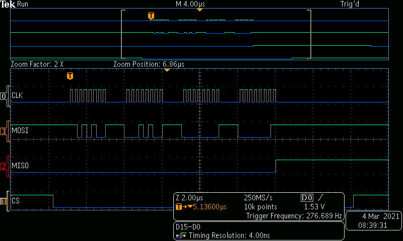
Following picture shows corresponding waveform when there is no input (No Load at Transducer) for ADS8681
References which i used :
1] ADS8681: Configuration Issues
2] ADS8691: how to read register value of bit[0:15]
3] ADS8689: 32 bits register reading command sequence
4] ADS8681: Problems to configure ADS 8681 to a Arduino MKW 1010 Wifi via SPI
5] ADS8681
Source code :
#include <SPI.h>
#include <LiquidCrystal.h>

#define SS 53
#define SCK 52
#define MOSI 51
#define MISO 50

uint16_t receivedVal16 = 0 ;

LiquidCrystal lcd (38,37,36,35,34,33);

void setup()
{
 lcd.begin(16,4);
 SPI.begin();
 SPI.setBitOrder(MSBFIRST);
 SPI.setDataMode(SPI_MODE0);

 digitalWrite(SCK,OUTPUT);
 digitalWrite(MOSI,OUTPUT);
 digitalWrite(SS,OUTPUT);
 digitalWrite(MISO,INPUT);

digitalWrite(SS, HIGH); //Write RANGE_SEL_REG
delay(10);
digitalWrite(SS,LOW);
SPI.transfer(0xD4);
SPI.transfer(0x14);
SPI.transfer(0x00);
SPI.transfer(0x01);

digitalWrite(SS, HIGH); //Write DATA_OUT_CNT_REG
delay(10);
digitalWrite(SS,LOW);
SPI.transfer(0xD4);
SPI.transfer(0x10);
SPI.transfer(0x41);
SPI.transfer(0x00);
}

void loop()
{
digitalWrite(SS, HIGH); //Write RANGE_SEL_REG
delay(10);
digitalWrite(SS,LOW);
SPI.transfer(0xD4);
SPI.transfer(0x14);
SPI.transfer(0x00);
SPI.transfer(0x01);


digitalWrite(SS, HIGH);
delay(10);
digitalWrite(SS,LOW);

receivedVal16 = SPI.transfer16(0x00);
lcd.setCursor(0,1);
lcd.print(receivedVal16);

delay(100);
}

