This thread has been locked.

If you have a related question, please click the "Ask a related question" button in the top right corner. The newly created question will be automatically linked to this question.

DAC161S997: Self-powered application schematic

Part Number: DAC161S997

Hi, 

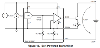
I have a customer case that is looking to use the self powered approach for this device, but there is some confision about how all of the GNDs need to be connected. Can you provide guidance on if there are any specific rules to follow?

For example, are COMA and COMD connected to the VD supply GND? Does VD GND need to be capacitively isolated from the loop GND?

If you have an example schematic to follow that  would help. I checked the EVM schematic but this looks to be configured in a loop powered config.

Thanks, 

Jose


  • Jose,


    With the self-powered transmitter, I refer back to Figure 16. I've clipped out a section of it and shown it below:

    For this to operate the LOOP supply ground (OUT,LOOP-) must be floating with respect the the device ground (GND, COMA). In this way, OUT will be allowed to drop slightly below COMA. Note that the voltage difference will be R2*I2. R2 is the internal 40Ω resistor and I2 basically is the loop current (really the loop current is IE+IDAC which is close to IE).


    Joseph Wu

  • Hi Joseph, 

    Thank you for the feedback. When referencing Figure 16, to confirm, does this mean that COMA, COMD, and GND are all tied together, and the only thing that needs to be isolated is the loop itself as you mentioned?  Since i dont see the COMD, I assume it is implied through the  way the block diagram is draw that it is the connection on the left hand side of the "IC" and this shows that COMA and COMD can/should be connected together?

    Thanks, 

    Jose

  • Jose,

    Yes, COMA and COMD should be connected together. If you look at the recommended operating conditions table in the datasheet, you'll see that COMA to COMD should be 0V. It's shown below:

    Joseph Wu