This thread has been locked.

If you have a related question, please click the "Ask a related question" button in the top right corner. The newly created question will be automatically linked to this question.

DAC8742H: Issues reading from the Rx FIFOs over SPI when using the DAC8742H in HART mode

Part Number: DAC8742H

Customer is having issues reading from the Rx FIFOs over SPI when using the DAC8742H in HART mode, although they appear to be able send data to the Rx FIFOs and initiate a HART transmission.

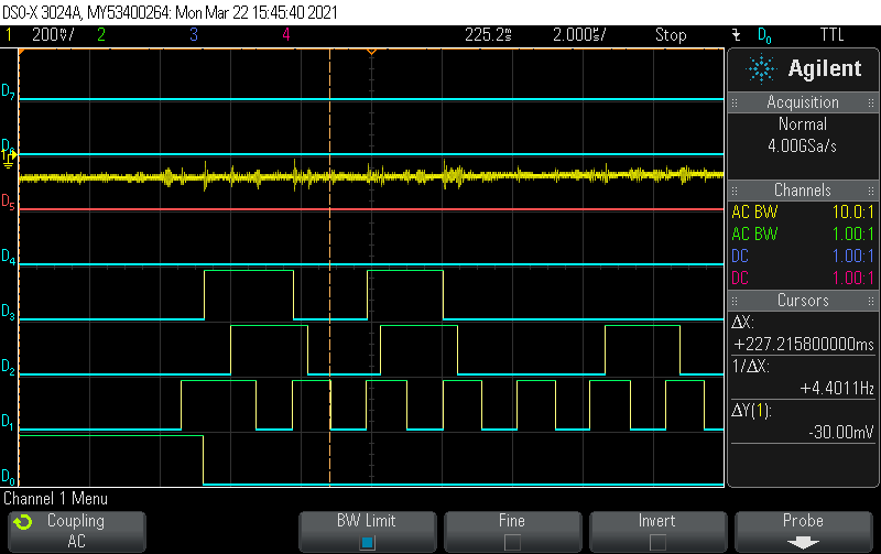
In there system, the SPI clock is ~500kHz, and the gap between successive SPI frames is greater than 3usec. The SPI read request interval is 60usec, so this significantly exceeds the required minimum of 2.442 usec between SPI frames

In there test code, They send two consecutive MODEM_STATUS read requests: 0xA00000

The response received during transmission of the 2nd read request is 0xA04044, indicating FIFO_M2D is FULL, and FIFO_D2M is EMPTY.

They send 4 consecutive FIFO_M2D Register read requests: 0xA40000

The responses received are:
0xA04044
0xA405FF
0xA405FF
0xA405FF

The first of the 4 is the response from the 2nd status read request.

The other 3 responses indicate FULL_FLAG and FIFO_LEVEL = 0. They suppose the FIFO_LEVEL has simply overflowed and can't represent a fill level of 16. However, why does the reported FIFO_LEVEL not decrement with each consecutive read request? Also, the HART data byte is always 0xff, regardless of how many bytes they try to read.

  • Hi Jonathan,

    Can they capture an SPI frame with an oscilloscope to confirm the timing and edge relationship is correct?

  • start of SPI frame is captured and attached.  D0 is ChipSelect;  D1 is SCLK (bit banged, so not perfect);  D2 is SDI (MOSI);  D3 is SDO (MISO).  SCLK frequency is ~500kHz.

    I transition MOSI data following rising edge of SCLK and sample MISO data on falling edge of SCLK.

  • Bill,


    I'm sorry I didn't get a chance to look at this earlier, but I didn't see anything wrong with the basic SPI. For this device, the data is setup on the rising edges of SCLK and clocked in and out of the device on the falling edges. Other than that, your SPI is running at 500kHz, which is a bit slow to really have problems with any other timing.

    I'll review this again tomorrow and see if I can come up with something to check.

    Joseph Wu

  • Any update?  I've not been able to resolve myself.   

    I have confirmed that when I send HART commands, the SPI echo of the register writes matches, confirming my SPI receive path is operating properly. Also, the field HART device is responding to my command as expected, giving further confidence that my SPI write procedures are working properly.

    I have interfaced to the EVM board for this device and a custom integration. Same results are observed on both.  Also, I have been able to get UART mode working properly on both the EVM and custom integration platforms.  Unfortunately, I need SPI operation and it just doesn't work.

    Can you confirm that my simple test procedure above is valid?  That is, sending a MODEM_STATUS read request followed by multiple FIFO_M2D read requests?  Also, is it expected that the FIFO_LEVEL be reported as 0 when the FULL_FLAG is set?

    While I'm asking questions, is the FIFO_LEVEL reported in response to a FIFO_M2D read request indicate the level before or after accounting for the data value being reported (i.e., when reading from a full fifo, is the reported fifo level 15 or 16/0)?

  • Bill,

    Sorry, there's been a lot going on, so I'm a bit behind on all the support lately. I did discuss this one with design but I haven't had a chance to really look over their response. I'll get back to you tomorrow.

    Joseph Wu


  • Bill,

    I ran a quick test with the EVM, setting up the device in SPI mode. For the HART write, I set up an array with 16 bytes to send to the device:

    0F 1F 2F 3F 4F 5F 6F 7F 8F 9F AF BF CF DF EF FF

    I then generate this write. Then I start another write of a single byte of 01 so that I'm sure to fill the buffer.

    When I start the the read, I receive 040F, indicating the full buffer. The next subsequent reads go through the elements of the buffer.

    A4F01F A4E02F A4D03F A4C04F A4B05F A4A06F A4907F A4808F A4709F A460AF A450BF A440CF A430DF A420EF A1010

    At the end I get A4020F as the buffer becomes empty. Subsequent reads return the last element of the buffer, so this read doesn't change. The last two reads look like they've been swapped, so I'll need to look into that and see if this is an artifact in the GUI or if there's something else going on.

    Regardless, the full buffer is indicated by the FULL_FLAG, and that the FIFO level is at 0. I would note that I do have some significant time from this full reading to the next set of 16 reads as I read through the buffer. When I checked with design, he had run a quick simulation that indicated that the FULL_FLAG also showed the FIFO level at 0 and then subsequent reads decrementing the FIFO level output. He had run through a set of four reads of FIFO_M2D.

    Joseph Wu

  • Clearly I have a fundamental problem as I can't even replicate your experiment.  I presume that you are using the modem in FIFO loop-back mode.

    Is it possible to send me the complete set of SPI transmission frames and corresponding read frames, including all configuration messages?  Please send the full frame info (i.e., 3-bytes), not just the data byte.  I will implement that exact sequence as a test.

    Thanks.

  • Bill,

    I got a logic analyzer and looked at the SPI going into and out of the device. I basically repeated the same experiment that I explained above. It looks like the GUI doesn't let you write too many bytes to the FIFO unless you just give another write to the device. This is what the sequence looks like:

    Words are separated by ~10ms, SCLK ~48kHz

    Write to device:
    DIN: 25 00 0F
    DIN: 23 00 0F
    DIN: 23 00 1F
    DIN: 23 00 2F
    DIN: 23 00 3F
    DIN: 23 00 4F
    DIN: 23 00 5F
    DIN: 23 00 6F
    DIN: 23 00 7F
    DIN: 23 00 8F
    DIN: 23 00 9F
    DIN: 23 00 AF
    DIN: 23 00 BF
    DIN: 23 00 CF
    DIN: 23 00 DF
    DIN: 23 00 EF
    DIN: 22 00 0D // No FF write
    DIN: 22 00 0C
    Now write one more byte:
    DIN: 25 00 01
    DIN: 23 00 01
    DIN: 22 00 0D
    DIN: 22 00 0C

    Now start read. I asked the GUI for 16, but it found the FIFO full and stopped the read.
    DIN: A4 FF FF 00 00 00
    DOUT: FF FF FF A4 04 0F //FIFO full

    Then I ask for another read. Read are in pairs. Pairs are separated by ~10ms, while each read is separated by ~150ms
    DIN: A4 FF FF 00 00 00
    DOUT: FF FF FF A4 F0 1F
    DIN: A4 FF FF 00 00 00
    DOUT: FF FF FF A4 E0 2F
    DIN: A4 FF FF 00 00 00
    DOUT: FF FF FF A4 D0 3F
    DIN: A4 FF FF 00 00 00
    DOUT: FF FF FF A4 C0 4F
    DIN: A4 FF FF 00 00 00
    DOUT: FF FF FF A4 B0 5F
    DIN: A4 FF FF 00 00 00
    DOUT: FF FF FF A4 A0 6F
    DIN: A4 FF FF 00 00 00
    DOUT: FF FF FF A4 90 7F
    DIN: A4 FF FF 00 00 00
    DOUT: FF FF FF A4 80 8F
    DIN: A4 FF FF 00 00 00
    DOUT: FF FF FF A4 70 9F
    DIN: A4 FF FF 00 00 00
    DOUT: FF FF FF A4 60 AF
    DIN: A4 FF FF 00 00 00
    DOUT: FF FF FF A4 50 BF
    DIN: A4 FF FF 00 00 00
    DOUT: FF FF FF A4 40 CF
    DIN: A4 FF FF 00 00 00
    DOUT: FF FF FF A4 30 DF
    DIN: A4 FF FF 00 00 00
    DOUT: FF FF FF A4 20 EF
    DIN: A4 FF FF 00 00 00
    DOUT: FF FF FF A4 10 00
    DIN: A4 FF FF 00 00 00
    DOUT: FF FF FF A4 02 0F

    Joseph Wu

  • Hi Joseph,

    With the help of your listing, I finally resolved the problem, although it took a while to replicate your results. One key element to the loopback test is that the loop back occurs only after RTS is enabled, and appears to get clocked at HART rates (i.e., one byte per ~9.2msec). In hindsight, that's reasonable, but certainly not documented in the datasheet.

    The key to resolving my issue is the observation that you are using the NOP function (0x00 00 00) to clock out the result of each and every FIFO read request (0xA4 FF FF). While this is OK, it is clearly not documented as required in the datasheet ... In fact, quite the opposite. The 2nd paragraph of Section 7.4.5.2 includes the statement "SDO will always provide information from the previous frame, if the previous frame was a read then the output data will be the requested data." This statement is clearly wrong, the NOP command must be used to get the results of the read command.

    I'm absolutely stunned that no one has run into this problem before. Please have an errata released for the datasheet.

    -Bill

  • Bill,

    Thanks for the response. I'm glad that you were able to get data from the device. I'll try to have the datasheet edited to be more clear. Generally, we don't have errata sheets. We collect updates and errors like this and roll a revision to the datasheet when we are able to.

    Let me know if you have any other questions or comments. Feel free to post back or start another thread.


    Joseph Wu