


Summary of Problem:
I am getting inaccurate readings using the TLV2553 in 8-bit precision mode despite verifying all of my connections and transmitting in 8-bit mode using CS as illustrated in Figure 3 of rev C of the datasheet. I've described my setup and included screenshots from my logic analyzer program below.
Setup:
Vcc is set at 5V, REF+ is set at 2.5V, and REF- is connected to ground. I have supplied a voltage of about 1.02 V to all of the AIN pins. The SPI lines and EOC are connected to an Atmega microcontroller with MISO and EOC configured as inputs on the Atmega and all others are configured as outputs. I have my SPI configured so that SCK idles low, SCK frequency is 250 kHz, MOSI is MSB, and data is valid on the rising edge of SCK (data transitions on the falling edge of SCK). I send two bytes with hex value 0x04 separated by a ~30us gap so that I can specify the analog channel and then read the second result. According to the datasheet, 0x04 should address analog channel 0, set the precision to 8 bits, set the bit order to MSB, and set the output format to unipolar binary.
Result:
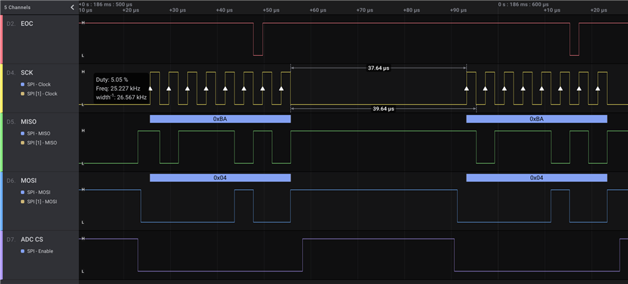
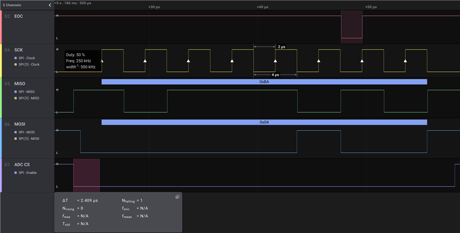
The result that I read in from my test is 186 (decimal) when I would expect something close to 100 (decimal) since the analog input is 1.02V and REF+ is 2.5V which is about 40% the ref value and 100 is closish to 40% of 255 which would be the max unipolar value for an 8-bit value. The result value does not change significantly as I increase or decrease the AIN0 input voltage. The screenshots below show the timing of the signals and everything looks to be within the specified timing constraints for operating with Vcc = 5V. One of the strange behaviors I've seen is that EOC drops low for a few microsecond before the eight falling edge of the clock but the datasheet led me to believe that EOC shouldn't go low until after the last SCK falling edge.
Additional Information:
I have tried many variations on my SPI configuration by adjusting the frequency, clock phase, etc. with no avail. I have tried keeping chip select low all the time which did not help. If I try using the 16-bit precision as shown in figure 5 I get all 0xFF responses, but if I use 12-bit precision (write 0x00) with only 8 clock pulses (I have no easy way of generating only 12 clock cycles with an 8-bit AVR microcontroller) then I get reasonable values for AIN0 and a couple of other channels, but the test registers and several other AIN channels are still way off and oscillate between 0 and 255.
I'm willing to provide any other information that will be helpful in troubleshooting the issue. I didn't see any other tickets addressing similar issues so perhaps I have somehow damaged my part, but it's strange that the part seems to demonstrate partial functionality as opposed to no response whatsoever. Thanks in advance for your time and help.

