Other Parts Discussed in Thread: TMUX7219
Hi guys.
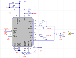
I have PN DAC8760.
There isn't a polarized connector to avoid accidental connection on 4-20mA output on the board.
Is there a method to protect 4-20mA output against accidental connection to power supply voltage (+12V/+24V)?
If it is possible I would apply the protection between my board and customer's cable (eg. series diode on 4-20mA output?).
Thanks.
Gabriele.