Other Parts Discussed in Thread: THS4531, LMH6551
We designed a data aquesition board for 24 channels using three ADS5270.
The ADS5270 are connected to an FPGA via LVDS and that interface is working fine.
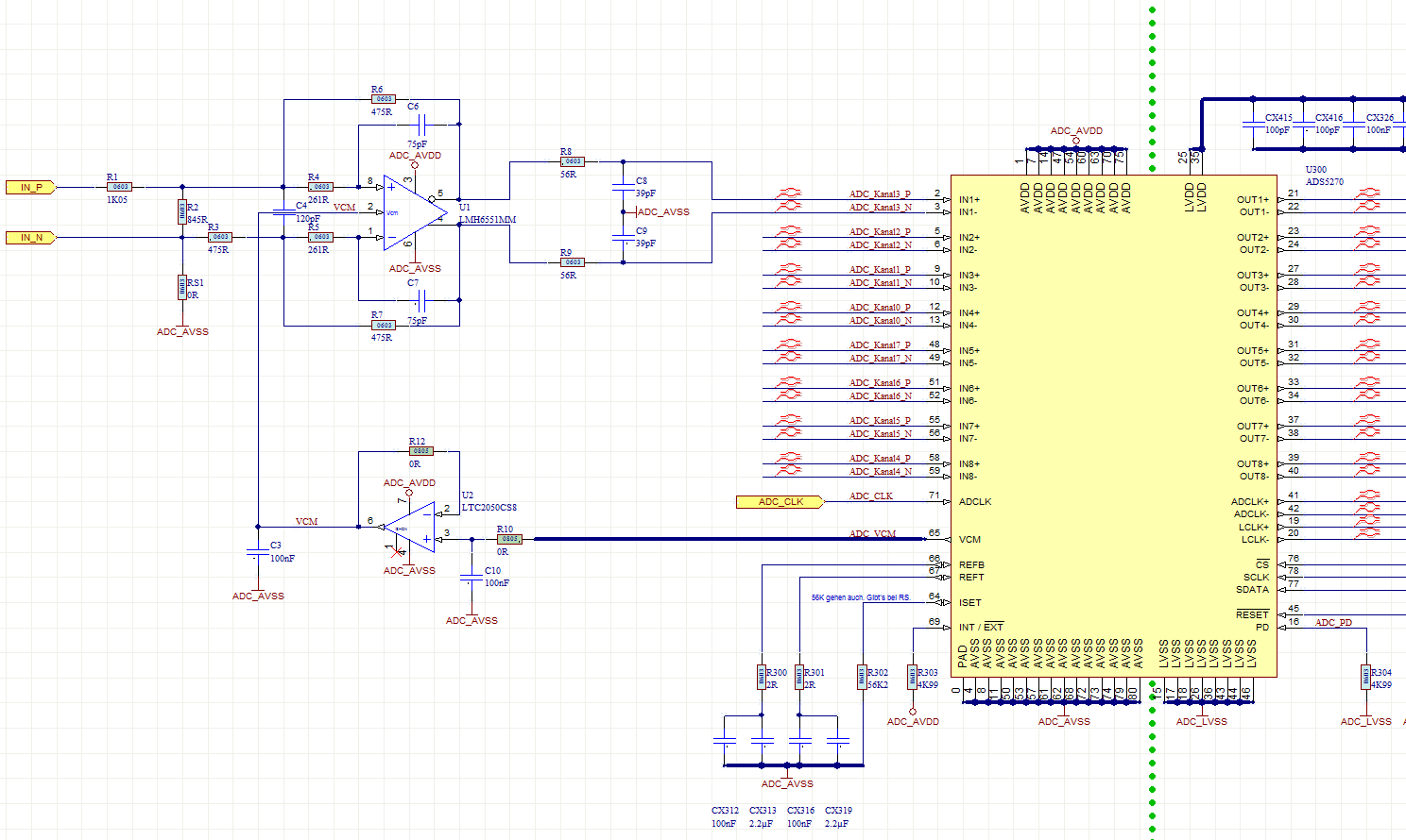
The PDF shows the schematics - how we connect to the ADS5270.
Our signals are comming from OpAmps outputs. These OpAmps have a +/-5V dual power supply.
The output signals are max. 5Vss (AC-coupled).
These signals are connected via a voltage divider to differential OpAmps (3.3V single supply) and then connected to the ADC.
For each ADC we buffer the VCM output of the ADC and feed it to 8 differential OpAmps.
Now on some boards and some ADCs we noticed that the VCM does not come up correctly.
In the oscillograms you see the VCM outputs of three ADCs on one PCB during startup.
Blue and yellow rise to 1.45V – as expected.
But green got stuck at around 600mV.
Thus rendering the measurement values useless.
PS: we can observe the same problems if we shorten the input of the voltage divider.
So we think the dual supply opamp stage is not causing the problem.
Did we do something wrong with schematics?
Is there an errata fort he ADS507x devices?
Thanks a million,
Steven