This thread has been locked.

If you have a related question, please click the "Ask a related question" button in the top right corner. The newly created question will be automatically linked to this question.

ADC12DJ3200: timestamp input common mode and capacitor before balun

Part Number: ADC12DJ3200
Other Parts Discussed in Thread: TSW14J57EVM

Hi TI,

We are using ADC12DJ3200 in our project.

ADC12DJ3200 will be interfaced with virtex-7 XC7VX485T FPGA.

We have two questions:

1. Common mode voltage for timestamp input in ADC12DJ3200 datasheet is 0.3v typical.

  We will be connecting the timestamp inputs of ADC12DJ3200 to virtex-7 FPGA using LVDS standard in FPGA.

  Now the common mode for LVDS output of FPGA is 1.25v.

  So, do we need to AC couple the timestamp inputs and provide the necessary common mode for timestamp inputs using pull up and pull down resistors on timestamp inputs?

  And if pull up resistors are required , which power supply should we use (1.9v analog, 1.1v analog, 1.1v digital) for pull ups?

2. We are using only balun (BAL-0009SMG) for input signal to ADC inputs. Do we also need to use capacitor between SMA connector and BALUN?

Thanks,

Lalit


  • Hi Lalit

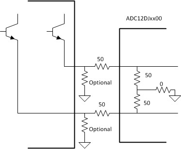
    1. Timestamp is generally driven by a low duty cycle or pulse type signal source. For this reason the connection should be DC-coupled to allow longer durations of static high or low. The best way to accomplish this is to use an LVDS to LVPECL buffer chip. I would recommend something like the MC100LVEP11 (1:2) or MC100LVEP16 (1:1) devices. The interface from the output of this buffer to the Timestamp input should be as shown below. In addition DC_LVPECL_EN control bit should be set to 1 to give the proper 50 ohm to ground internal termination in the ADC Timestamp inputs.

    2.  No AC-coupling capacitors are required between the SMA connector and the balun input.

    Best regards,

    Jim B

  • Hi Jim,
    Typical Common mode voltage for timestamp inputs in ADC12DJ3200 datasheet is 0.3v and maximum is 0.5v.
    I am not able to find the output common voltage in the datasheets of the buffers you suggested.
    I have also check the TSW14J57 EVM . The timestamp inputs from FPGA directly connects to ADC12DJ3200.
    How this is done ?
    Is common mode voltage of FPGA used in TSW14J57 is less than 0.5v?

    Please sugggest, how to connect timestamp inputs of ADC12DJ3200 with virtex-7 FPGA?

    Thanks,
    Lalit
  • Hi Lalit
    With the circuit shown and a 2.5V supply LVPECL driver like the one suggested the common mode voltage will still be slightly above 0.55V (around 0.58V typical). Changing the series resistors from 50 ohm to 75 ohm will change the divide ratio and give acceptable common mode and differential voltage levels at the ADC Timestamp inputs.
    While there are connections from the FMC connector of the EVM that interface to the TSW14J57EVM we haven't actually used that path for any function because of the common mode mismatch. It won't damage the ADC Timestamp input but won't work properly.
    I'm not aware of any differential output modes available in the Virtex-7 FPGA that are directly compatible with the Timestamp input. Some type of signal buffer like the one suggested must be used.
    Can you describe how you plan to use the timestamp signal in your system?
    Will the FPGA be generating a signal on the Timestamp pair that is synchronous to the ADC clock or serial data pairs?
    Best regards,
    Jim B