Hi,
I've been trying to control the ADS1255 for a while now and trying to read out the values. Unfortunately I still have problems.
To the setup: I have a board where an ATmega88 is the interface between ADS1255 and RS485 communication. The circuitry is taken from the schematic for the NIRscanNano and looks like this:

I read the following thread ( ) and took the code from this post (
 ).
).
#define F_CPU 11059200

#include <avr/io.h>
#include <util/delay.h>
#include <stdio.h>

#define BAUD 115200UL
#define UBRR0_Value (F_CPU/(16*BAUD)-1)
#define CS_LOW PORTB &= ~(1 << PB2);
#define CS_HIGH PORTB |= (1 << PB2);

//UART functions_________________________________________________________________

//________ Configure UART _______
void UART_init()
{
	UBRR0H = (unsigned char) (UBRR0_Value >> 8);
	UBRR0L = (unsigned char) UBRR0_Value;
	UCSR0B = (1<<TXEN0) | (1<<RXEN0);
	UCSR0C = (1<<UCSZ00) | (1<<UCSZ01);

}

// _____ Send char via UART ______
static void UART_transmit_char (unsigned char ch)
{
	while (!(UCSR0A & (1<<UDRE0)))
	{
		;
	}

	UDR0 = ch;
}

// ______ Send string via UART _____
static void UART_transmit_string (char * s)
{
	while (*s)
	{
		UART_transmit_char (*s);
		s++;
	}
}

// _____ Receive Byte via UART ____
char UART_receive(void)
{
	while(!(UCSR0A & (1<<RXC0)));
	return UDR0;
}

//end UART functions______________________________________________________________

// SPI functions__________________________________________________________________

// _____ Configure SPI ______
void SPI_Init()
{
	DDRB |= (1<<5)|(1<<3)|(1<<2);			 // MOSI, !CS , SCK as Output
	SPCR |= (1<<SPE)|(1<<MSTR)|(1<<SPR0)|(1<<CPHA);     // SPI Enable, SPI = Master, Prescaler = 16
}

// ____ Send SPI Data and return the received byte _____
unsigned char ADS1255_transceive (unsigned char data)
{
	SPDR = data;
	while(!(SPSR & (1<<SPIF) ));    // Wait until transmission complete
	_delay_us(20);					// wait for 10µ until DOUT (t6)
	return(SPDR);
}

//end SPI functions______________________________________________________________

// _____ Read register of ADS1255 and return register value _____
void ADS1255_Init()
{

	CS_LOW;

	ADS1255_transceive(0xFE);
	UART_transmit_string("ADS1255 RESET");
	UART_transmit_char('\r');
	_delay_us(5);

	ADS1255_transceive(0xF);
	UART_transmit_string("ADS1255 SDATAC");
	UART_transmit_char('\r');
	_delay_us(10);

	CS_HIGH;

}

int32_t ADS1255_Read_Data()
{

	int32_t result = 0;
	uint8_t ADC_bytes[3];

	CS_LOW;
	_delay_us(5);
	ADS1255_transceive(0x01);

	ADC_bytes[0] = ADS1255_transceive(0);
	ADC_bytes[1] = ADS1255_transceive(0);
	ADC_bytes[2] = ADS1255_transceive(0);
	_delay_us(10);

	CS_HIGH;
	_delay_us(5);

	if (ADC_bytes[0] & 0x80)     //  negativ
	{
		result = (int32_t) (((0xFF)<<24)|((ADC_bytes[0]&0xFF)<<16)|
		((ADC_bytes[1]&0xFF)<<8)|
		((ADC_bytes[2]&0xFF)<<0));
	}
	else						 // positiv
	{
		result = (int32_t) (((0x00)<<24)|((ADC_bytes[0] & 0xFF)<<16)|
		((ADC_bytes[1] & 0xFF)<<8)|
		((ADC_bytes[2] & 0xFF)<<0));
	}

	return result;
}


// Main funcion _____________________________________________________________________
int main(void)
{
	_delay_ms(3000);   // startup delay

	UART_init();
	SPI_Init();
	ADS1255_Init();

	while(1)
	{
		ADS1255_Read_Data();				// read ADC data
		_delay_ms(1000);
	}
}
Unfortunately I get an answer from the converter, which I did not expect and after that I don't get any answers anymore. The DRDY signal is always high. Maybe somebody else has tips or advice on how to get reasonable values from the ADS1255.
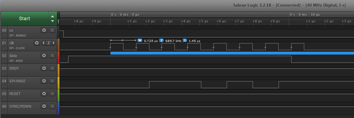
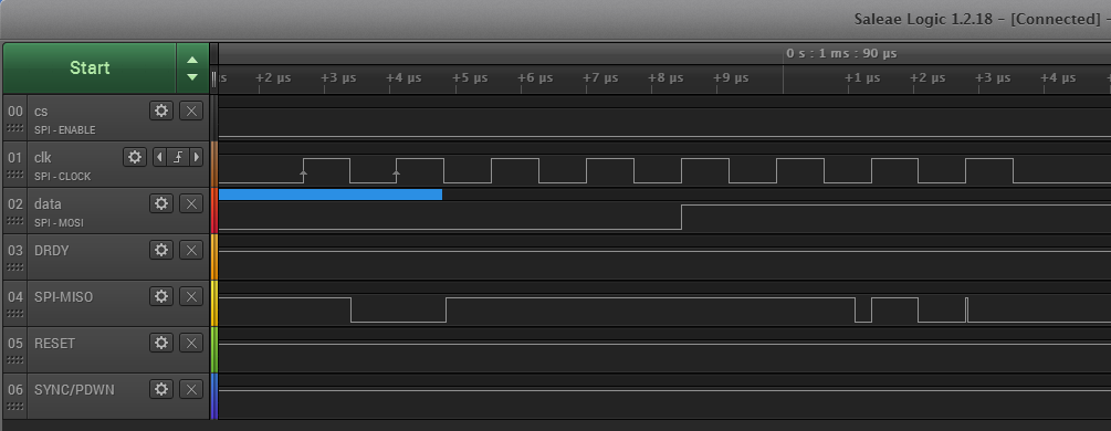
Here are the first three commands recorded with my LogicAnalyser:
Command: 0xFE (RESET)
Command: 0x0F (SDATAC)

Command: 0x01, 0x00, 0x00 0x00 (RDATA, Read, Read, Read)
I hope someone has some advice or tips for me.
Best regards
Michael


