This thread has been locked.

If you have a related question, please click the "Ask a related question" button in the top right corner. The newly created question will be automatically linked to this question.

TINA/Spice/LM25119: PSPICE Model -- Gross Errors

Part Number: LM25119
Other Parts Discussed in Thread: TINA-TI,

Tool/software: TINA-TI or Spice Models

The model that is provided for this device, http://www.ti.com/lit/zip/snvm865 appears to have gross errors that preclude its usefulness as a general purpose simulation model.

It would take far more time than I can afford, to fully enumerate all the details of this model.  That said, any single one of these is enough to illustrate a failing of the model, if not a fatal error.

1. There are no disclaimers or approximations noted in the header of the file.  Clearly, this model will have significant limitations.  How is the end user supposed to know what those are?

2. The COMP and COMP2 pins are driven by E sources with zero output resistance.  This violates the datasheet COMP VOH and COMP VOL parameters, and prevents simulation of ganged operation (singular matrix).  Furthermore, there is no disable function on this pin, which apparently is triggered by setting FB(n) = VCC(n).

3. SS and SS2 are driven by a G source (10 or 1 microampere) and no clamping voltage.  I cannot see another load for these nets that would act to limit their voltage.  The datasheet gives an absolute maximum of 7V, which will be exceeded quickly (hundreds of milliseconds) with a typical SS capacitor, 1uA charge current, and no limiting voltage.  The only other connection to these nets, a  _S5_mod switch, specifies 1mohm on resistance, a clearly bogus figure.

4. VIN current appears to be zero, i.e., I_BIAS is not modeled at all.  This violates four lines on the datasheet, and makes it impossible to simulate device power dissipation.

5. RT appears to be driven by a current and nothing else (IS1#CLK_GEN), which violates the datasheet (RT output voltage typ 1.25V at RT = 25k).

These mistakes are fundamental to the model itself, part of SPICE syntax, independent of simulator.

While I am not using PSPICE to investigate this model, I am also not expecting (or complaining about) the model not working in my particular simulator.

If you could provide a netlist of a working PSPICE test simulation, using this model, that would be helpful.

Thank you,

Tim

  • Hi Tim,

    Thank you so much for your suggestion. We will evaluate the model and try to incorporate the changes, if needed.

    Also, I have attached a working netlist of PSpice test simulation as per your request. Please let us know if you have any other queries.

    Thanks,
    SomenLM25119_TRANS.cir

  • I have reconstructed the supporting netlist as accurately as I can, and the core model still does not work. Thanks anyway.
  • Hi Tim,

    Kindly share what specific issues you are facing. The netlist that we have shared with you will work in PSpice 15.7 and above.

    Thanks,
    Somen
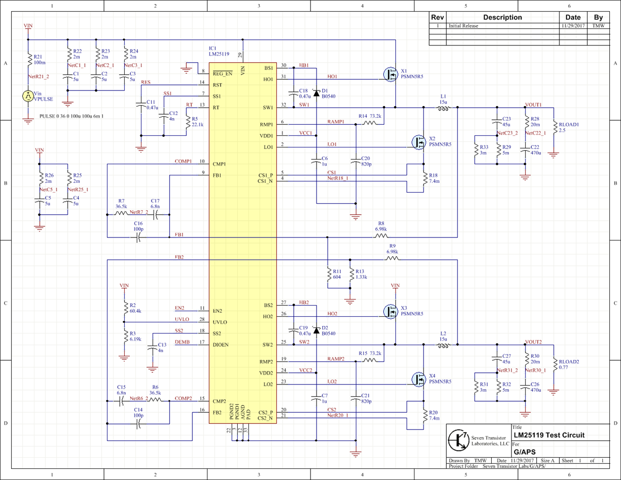
  • I have recreated the netlist as accurately as I can tell (aside from the diodes being a different model I had handy, because who cares).  Schematic:

    I've set the simulation parameters the same, and get the error,

    [Warning] singular matrix:  check nodes b_bvccx\xic1#branch and b_bvccx\xic1#branch

    [Error] doAnalyses: Timestep too small

    This is more as an example, than a specific error I'm having trouble with.  If I get a singular matrix error, it seems to pick a node randomly.  (This may be a simulator problem.  I've noticed inconsistent behavior before.)

    I've made numerous changes to the model over the last few weeks, converting PSPICE syntax and working to eliminate those terrible discontinuous IF statements.  At one point, I had it working without errors; there was no output.  Snooping around within the LM25119 SUBCKT, the CLK seems to drive all other functions, and it wasn't producing a signal.  I made this change,

    .SUBCKT CLK_GEN RT CLK
    IS1 0 RT 1U
    XU4 6 5 RT VCR_1
    XU6 4 3 RT VCR_0
    DU5 4 3 DD1
    C2 3 0 1U IC=1
    *XU2 5 4 INV_0
    XU2 5 4 BEH_NOT2 PARAMS: THRESHOLD=0 OUTRES=10m CDELAY=4p GAIN=1k VDD=12 VSS=-12
    R5 6 0 1G
    C1 6 0 1U IC=1
    *XU3 5 3 CLK AND_0
    XU3 5 3 CLK BEH_AND2 PARAMS: THRESHOLD=0 OUTRES=10m CDELAY=4p GAIN=10k VDD=3.5 VSS=0.3
    *XU1 7 6 5 COMPARATOR_0
    XU1 7 6 5 BEH_COMP2 PARAMS: OUTRES=10m CDELAY=4p GAIN=10k VDD=12 VSS=-12
    R2 0 7 1K
    R1 7 5 1K
    .MODEL DD1 D (RS=0.1m N=0.1m)
    .ENDS

    Replacing the discontinuous statements with a continuous, formula-free equivalent.  Only the inverter is quoted below, but the others are constructed similarly.

    .SUBCKT BEH_NOT2 A Y PARAMS: Threshold=2.5V OutRes=100 Cdelay=100p Gain=1k VDD=5.0 VSS=0.0
    CA INA 0 {Cdelay}
    CG GAIN VSS {Cdelay/5}
    D1 VDIO 0 IDEALD TEMP=23
    D2 GAIN VDIO_PR IDEALD TEMP=23
    D3 0 INA IDEALD TEMP=23
    D4 INA 0 IDEALD TEMP=23
    D7 VDIO_NR GAIN IDEALD TEMP=23
    E1 VDD VDIO_P VDIO 0 1.0
    E2 GB VSS GAIN VSS 1.0
    E3 VDIO_N VSS VDIO 0 1.0
    G1 INA 0 A TH -1.0m
    G3 GAIN VSS INA 0 1.0m
    I1 0 VDIO 1.0m
    RA INA 0 {1k*Gain^(1/2)}
    RG GAIN VSS {1k*Gain^(1/2)}
    RD2 VDIO_P VDIO_PR 1.0
    RD7 VDIO_N VDIO_NR 1.0
    RY GB Y {OutRes}
    VTH TH 0 {Threshold}
    VVDD VDD 0 {VDD}
    VVSS VSS 0 {VSS}
    .MODEL IDEALD D ( IS=1p N=1.8 RS=1m XTI=0 )
    .ENDS

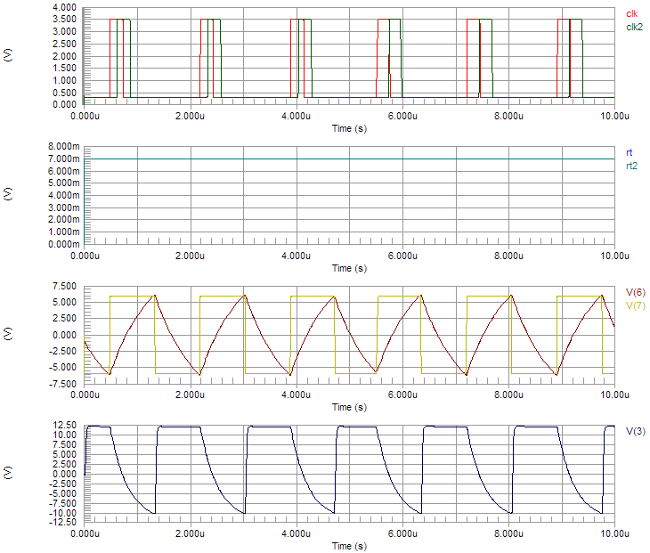
    This yielded a working CLK_GEN subcircuit:

    (clk2 and rt2 are from the SUBCKT above, while the other waveforms come from a schematic equivalent model of CLK_GEN.  There is a small timing difference, but they both operate effectively at least.)

     The rest of the LM25119 is not working at this time.  There are many, many statements left to convert.

    As you might surmise, my suspicion is the abundance of discontinuous statements.  AFAIK, those are bad enough even in PSPICE, but they're utterly unworkable in anything else.  They certainly preclude GEAR integration, necessary for obtaining usefully clean switching waveforms.

    Tim

  • Hi Tim,

    Could you please confirm which simulator are you using? We support PSpice and TINA-TI simulations, both of which are already setup and provided on the web. www.ti.com/.../toolssoftware. I would recommend using one of these as a starting point.

    If you are new to TINA-TI, it is a free simulator from TI and the short video training series will help you get ramped up on this.

    Thanks,
    Somen