This thread has been locked.

If you have a related question, please click the "Ask a related question" button in the top right corner. The newly created question will be automatically linked to this question.

DLPDLCR230NPEVM: Only green LED is displaying with sample scripts

Part Number: DLPDLCR230NPEVM
Other Parts Discussed in Thread: DLPC3436
Hello TI Team,

We just started working with a DLPDLCR230NPEVM and started off by running the python scripts.  The sample02_splash.py is working fantastically - all of the colors are vivid and bright.  However, once we attempt to display the raspberry pi desktop or an .mp4 from the Rpi, the image shows up all green.  It seems that only the green LED is activated when displaying directly from the Rpi. What might be the reason for this?

As I mentioned, all of the LED's are activated for the "splash" screen sample.  However, the RED and BLUE LED's are not activated for several of the other sample python scripts.  For example, "sample01_tpg.py" will show an all green screen when "white" is listed as being displayed.  Most of the display tests only show green, or show black when either Red or Blue are intended to be displayed.  Notably, the"actuator" test seems to display correctly, with all of the colors (RGB) showing within each pixel.  Also notably, when sample03_display.py is run, all of the test colors for "Cycling Image Curtain Settings" are correct.  RGB, Cyan, Magenta, etc all fill the screen.  Then lastly, when sample05_led.py is run, the Red and Blue tests do have visible light, it's just not filling any part of the screen like with the green test and what is visible is incredibly dim.
Process & Background:
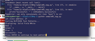
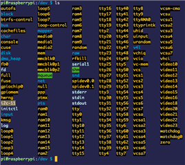
For our setup, we replaced the config.txt in /boot with the sample config.txt provided along with the python api.  The only change that was made was to change the DEFAULT_SLAVE_ADDRESS value in i2c.py from 7 to 11, to match the i2c device in /dev .  This change was made after running "init_parallel_mode.py" as described in the manual and encountering an error having to do with the wrong i2c address. "No such file or directory: '/dev/i2c-7'".  The error was fixed by changing this value.  All of the scripts run, but Red and Blue are not activated in many of them.

We do intend to use a Raspberry Pi Zero W 2 in place of the 4B+, however we have tested with both the Zero and the 4B+ and the green LED issue remains the exact same (we simply replaced microSD card).  The Rpi Zero W 2 is connected via a soldered female header and 4B+ is connected via the header connector that was provided with the EVM.
Indicators:
D_DONE and D_INI_B_LED are on and D_HOST_IRQ is off.

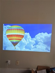
Example of Splash Screen displaying with all colors:
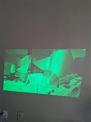
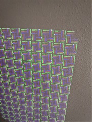
Video played with mplayer:

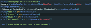
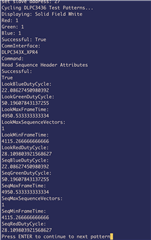
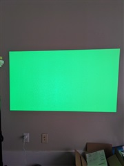
sample01 - "Displaying: Solid Field White":

"Actuator Test Pattern"
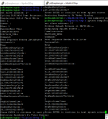
The outputs of the status registers:

config.txt:
# For more options and information see
# http://rpf.io/configtxt
# Some settings may impact device functionality. See link above for details

# #########################################
# DO NOT MODIFY THE LINES BELOW THIS POINT
# #########################################

# uncomment if you get no picture on HDMI for a default "safe" mode
#hdmi_safe=1

# uncomment this if your display has a black border of unused pixels visible
# and your display can output without overscan
disable_overscan=1

# uncomment the following to adjust overscan. Use positive numbers if console
# goes off screen, and negative if there is too much border
#overscan_left=16
#overscan_right=16
#overscan_top=16
#overscan_bottom=16

# uncomment to force a console size. By default it will be display's size minus
# overscan.
#framebuffer_width=1280
#framebuffer_height=720

# uncomment if hdmi display is not detected and composite is being output
hdmi_force_hotplug=1

# uncomment to force a specific HDMI mode (this will force VGA)
hdmi_group=2
hdmi_mode=82

# uncomment to force a HDMI mode rather than DVI. This can make audio work in
# DMT (computer monitor) modes
#hdmi_drive=2

# uncomment to increase signal to HDMI, if you have interference, blanking, or
# no display
config_hdmi_boost=4

# uncomment for composite PAL
#sdtv_mode=2

#uncomment to overclock the arm. 700 MHz is the default.
#arm_freq=800

# Additional overlays and parameters are documented /boot/overlays/README

# Enable audio (loads snd_bcm2835)
dtparam=audio=on

# Uncomment this to enable infrared communication.
#dtoverlay=gpio-ir,gpio_pin=17
#dtoverlay=gpio-ir-tx,gpio_pin=18

# #########################################
# DO NOT MODIFY THE LINES ABOVE THIS POINT
# #########################################

# Uncomment some or all of these to enable the optional hardware interfaces
#dtparam=i2c_arm=on
#dtparam=i2s=on
dtparam=spi=on

# Configure Raspberry PI for SSH over USB
dtoverlay=dwc2

# Configure I2C on GPIO Pins #22 and #23
dtoverlay=i2c-gpio,i2c-gpio_sda=23,i2c_gpio_scl=22,i2c_gpio_delay_us=2

# Configure DPI on GPIO Pins #0 through #21
gpio=0=op
gpio=0=pn
gpio=1-27=ip
gpio=1-27=pn

# Enable DPI18 Overlay
enable_dpi_lcd=1
display_default_lcd=1
dpi_group=2
dpi_mode=87

# Configure DPI Video Timings
# RGB 666 CFG 1 (MODE 5)
dpi_output_format=458773 

# 58 Hz Timings (Low-End Spec)
# Works at GPIO DRIVE 5-7
hdmi_timings=1920 0 20 10 10 1080 0 10 10 10 0 0 0 58 0 125000000 3

# NOTE: GPIO PINS #24 - #27 ARE DRIVEN SEPARATELY BY WiringPi SOFTWARE

[pi4]
# Enable DRM VC4 V3D driver on top of the dispmanx display stack
#dtoverlay=vc4-fkms-v3d
#max_framebuffers=2

[all]
#dtoverlay=vc4-fkms-v3d


The power supply that we are using is from a Canakit, 5.1V 3.5A, which is within the recommended range listed on the EVM user manual.  Additionally, as far as I can tell, this would not explain why the colors show for the stills, and not the Rpi interface.
On another, less important note, the 'omxplayer' command was giving us an error out of the box.  Limited troubleshooting was done for this at present.  For now we used mplayer instead and it ran the .mp4, but again, without Red and Blue.  If you have any idea of what the issue may be we would appreciate guidance.
Thanks for your assistance,
Andrew
  • Status Registers:

    set slave address: 27
    Reading DLPC3436 Status Registers...
    ----------------------
    Short Status Register:
    {'SystemInitialized': 1,
    'CommunicationError': 0,
    'SystemError': 0,
    'FlashEraseComplete': 0,
    'FlashError': 0,
    'Application': 1,}
    ----------------------
    System Status Register:
    {'DmdDeviceError': 0,
    'DmdInterfaceError': 0,
    'DmdTrainingError': 0,
    'RedLedState': 1,
    'GreenLedState': 1,
    'BlueLedState': 1,
    'RedLedError': 0,
    'GreenLedError': 0,
    'BlueLedError': 0,
    'SequenceAbortError': 0,
    'SequenceError': 0,
    'SequenceBinNotFoundError': 0,
    'DcPowerSupply': 0,
    'ActuatorDriveEnable': 1,
    'ActuatorPwmGenSource1080POnly': 1,
    'ActuatorConfigurationError': 0,
    'ActuatorWatchdogTimerTimeout': 0,
    'ActuatorSubframeFilteredStatus': 0,}
    ----------------------
    Communication Status Register:
    {'InvalidCommandError': 0,
    'InvalidCommandParameterValue': 0,
    'CommandProcessingError': 0,
    'FlashBatchFileError': 0,
    'ReadCommandError': 0,
    'InvalidNumberOfCommandParameters': 0,
    'BusTimeoutByDisplayError': 0,
    'AbortedOpCode': 0,}
    ----------------------
    System Software Version Register:
    'Version':  2 . 1 . 3
    ----------------------
    Controller Device ID Register:
    {'_value_': 6,
    '_name_': 'Dlpc3436',}
    ----------------------
    DMD Device ID Register:
    'Device ID':  0x89000d60
    ----------------------
    Flash Build Version Register:
    'Version':  7 . 3 . 13
    ----------------------
    FPGA Version Register:
    'Version':  0x10001047 'Eco Revision':  0x0 'ARM SW Version':  0x0
    ----------------------
    FPGA Status Register:
    'XPR Status':  1 'Pass/Fail Status':  0
    

  • Hello Andrew,

    Welcome to DLP forum and thank you for your interest in DLP technology.

    Our team member will look into this get back to you by middle of next week.

    regards,

    Vivek

  • Hello Andrew,

    Thank you for your patience on this reply and the detailed explanation of your issue. I have been attempting to recreate this behavior on a new 230NPEVM and Raspberry Pi 4, but my system is not displaying the bug.

    There are three points I would like to test:

    1. Execute sample06_status.py during failure mode
      1. The sample01_tpg.py file may be altered to end on white tpg
      2. Paste contents in this thread to compare
    2. ReadRgbLedEnable() during failure mode to check status of red and blue LED's
      1. Force LEDs active with WriteRgbLedEnable(1,1,1) if inactive
      2. Re-read ReadRgbLedEnable() to check status of registers after forcing LED's
    3. Re-flash and configure Raspberry Pi boot contents
      1. It may be that the data has been corrupted on the Pi boot process. 

    Additionally, can you say how the EVM software package was uploaded to the Pi? Have you encountered any failures when running the scripts?

    Regards,

    Austin

  • Thank you Vivek and Austin for looking into this. 

    Here are the results from those tests:

    1.  Results from sample06_status.py during execution of modified sample01_tpg.py (failure state, "white" tpg.  Commented out other displays apart from white)

    set slave address: 27
    Reading DLPC3436 Status Registers...
    ----------------------
    Short Status Register:
    {'SystemInitialized': 1,
    'CommunicationError': 0,
    'SystemError': 0,
    'FlashEraseComplete': 0,
    'FlashError': 0,
    'Application': 1,}
    ----------------------
    System Status Register:
    {'DmdDeviceError': 0,
    'DmdInterfaceError': 0,
    'DmdTrainingError': 0,
    'RedLedState': 1,
    'GreenLedState': 1,
    'BlueLedState': 1,
    'RedLedError': 0,
    'GreenLedError': 0,
    'BlueLedError': 0,
    'SequenceAbortError': 0,
    'SequenceError': 0,
    'SequenceBinNotFoundError': 0,
    'DcPowerSupply': 0,
    'ActuatorDriveEnable': 1,
    'ActuatorPwmGenSource1080POnly': 1,
    'ActuatorConfigurationError': 0,
    'ActuatorWatchdogTimerTimeout': 0,
    'ActuatorSubframeFilteredStatus': 0,}
    ----------------------
    Communication Status Register:
    {'InvalidCommandError': 0,
    'InvalidCommandParameterValue': 0,
    'CommandProcessingError': 0,
    'FlashBatchFileError': 0,
    'ReadCommandError': 0,
    'InvalidNumberOfCommandParameters': 0,
    'BusTimeoutByDisplayError': 0,
    'AbortedOpCode': 0,}
    ----------------------
    System Software Version Register:
    'Version':  2 . 1 . 3
    ----------------------
    Controller Device ID Register:
    {'_value_': 6,
    '_name_': 'Dlpc3436',}
    ----------------------
    DMD Device ID Register:
    'Device ID':  0x89000d60
    ----------------------
    Flash Build Version Register:
    'Version':  7 . 3 . 13
    ----------------------
    FPGA Version Register:
    'Version':  0x10001047 'Eco Revision':  0x0 'ARM SW Version':  0x0
    ----------------------
    FPGA Status Register:
    'XPR Status':  1 'Pass/Fail Status':  0


    2.  Code for forcing LED's:

    Results:

    3.  Re-flash and configure Raspberry Pi boot contents

    /boot/config.txt was completely replaced with a newly downloaded 'sample_config' via microsd adapter as opposed to wirelessly.  Unfortunately, the same issues are occurring.

    As for how we uploaded the software package to the EVM, we used rsync with -avz flags.  There were no errors/failures when running any of the scripts once the i2c address was changed (the DEFAULT_SLAVE_ADDRESS change that was mentioned in the first post).

    - Andrew

  • Hello Andrew,

    Thank you for running these tests. This is peculiar behavior, so I have a more questions.

    Are there any other I2C files in /dev? Are you able to establish I2C communications if you select that address in place of 11? Does the performance improve?

    What Raspberry Pi OS version is loaded on your system? This can be checked with 'cat /etc/os-release' at the CLI.

    Do you have another EVM or Raspberry Pi on hand? If so, please try swapping in the Pi with the bugged EVM or the other EVM with the bugged Pi. This may help us determine if there is a hardware issue specific to your devices.

    Regards,

    Austin

  • Agreed, it's very odd.  Thanks for helping us think it through!  Here are the results:

    "Are there any other I2C files in /dev? Are you able to establish I2C communications if you select that address in place of 11? Does the performance improve?"

    From what I can tell there is only i2c-11.


    What Raspberry Pi OS version is loaded on your system? This can be checked with 'cat /etc/os-release' at the CLI.

    PRETTY_NAME="Raspbian GNU/Linux 11 (bullseye)"
    NAME="Raspbian GNU/Linux"
    VERSION_ID="11"
    VERSION="11 (bullseye)"
    VERSION_CODENAME=bullseye
    ID=raspbian
    ID_LIKE=debian
    HOME_URL="">http://www.raspbian.org/"
    SUPPORT_URL="
    ">www.raspbian.org/RaspbianForums"
    BUG_REPORT_URL="">www.raspbian.org/RaspbianBugs"

    Do you have another EVM or Raspberry Pi on hand?

    No extra EVM, but there is a Rpi 4B+ on hand.  This was the first Rpi that was attempted, with the same issue.  After re-flashing a new image on a separate microsd that was just formatted, I attempted to use the 4B+, but still the same green LED issue.

  • Andrew,

    Since both Raspberry Pis show this issue we can focus on the EVM.

    Please try the following:

    1. Issue ReadSequenceHeaderAttributes() command during normal operation and failure mode
      1. Is there any difference in any member of returned data?
    2. Reflash the FPGA binary using flash_write_fpga.py and retest
      1. The FPGA binary is included in the download package for the DLPC3436 on the TI Firmware Selector Tool
      2. It may be that the FPGA firmware has been corrupted

    Regards,

    Austin

  • 1.  "Issue ReadSequenceHeaderAttributes() command during normal operation and failure mode"


    "Is there any difference in any member of returned data?"

    I could not find any differences between normal op and failure mode.

    2.  "Reflash the FPGA binary using flash_write_fpga.py and retest"

    Did this with the following firmware, if anyone else is reading:


    And it did in fact successfully display the RPi UI and subsequently the mp4 using mplayer.

    Notably, on restart with 'shutdown -r' the same issue returns (only green LED).

    So I modified flash_fpga.py and removed the actual flashing process with 'flashrom'.  At that point it was re-writing identical data anyway.

    When I restarted and ran the modified flash_write_fpga.py it was again successful after init_parallel_mode.py was run.

    I'm going to share the modified file (simply added some comments) so that perhaps you can recommend a further reduction of the process.  This way, it will be possible to isolate whether the restart of the FPGA fixed the issue, or perhaps it was one of the other steps that still remain in the file:

    ###########################################################################################################################################################################
    # Texas Instruments DLP LightCrafter 230NP EVM Python Support Code - flash_write_fpga.py - Last Updated June 4th, 2020
    # This script is intended to be used with the DLPDLCR230NP EVM on a Raspberry Pi 4 (or compatible)
    # It is recommended to consult the DLPDLCR230NPEVM User's Guide for more detailed information on the operation of this EVM
    # For technical support beyond what is provided in the above documentation, direct inquiries to TI E2E Forums (http://e2e.ti.com/support/dlp)
    # 
    # Copyright (C) 2020 Texas Instruments Incorporated - http://www.ti.com/ 
    # 
    # Redistribution and use in source and binary forms, with or without modification, are permitted provided that the following conditions are met: 
    # 
    # Redistributions of source code must retain the above copyright notice, this list of conditions and the following disclaimer.
    # 
    # Redistributions in binary form must reproduce the above copyright notice, this list of conditions and the following disclaimer in the documentation 
    # and/or other materials provided with the distribution.
    # 
    # Neither the name of Texas Instruments Incorporated nor the names of its contributors may be used to endorse or promote products derived from this software 
    # without specific prior written permission.
    # 
    # THIS SOFTWARE IS PROVIDED BY THE COPYRIGHT HOLDERS AND CONTRIBUTORS "AS IS" AND ANY EXPRESS OR IMPLIED WARRANTIES, INCLUDING, BUT NOT LIMITED TO, THE 
    # IMPLIED WARRANTIES OF MERCHANTABILITY AND FITNESS FOR A PARTICULAR PURPOSE ARE DISCLAIMED. IN NO EVENT SHALL THE COPYRIGHT OWNER OR CONTRIBUTORS BE LIABLE 
    # FOR ANY DIRECT, INDIRECT, INCIDENTAL, SPECIAL, EXEMPLARY, OR CONSEQUENTIAL DAMAGES (INCLUDING, BUT NOT LIMITED TO, PROCUREMENT OF SUBSTITUTE GOODS OR SERVICES; 
    # LOSS OF USE, DATA, OR PROFITS; OR BUSINESS INTERRUPTION) HOWEVER CAUSED AND ON ANY THEORY OF LIABILITY, WHETHER IN CONTRACT, STRICT LIABILITY, OR TORT 
    # (INCLUDING NEGLIGENCE OR OTHERWISE) ARISING IN ANY WAY OUT OF THE USE OF THIS SOFTWARE, EVEN IF ADVISED OF THE POSSIBILITY OF SUCH DAMAGE.
    #
    ###########################################################################################################################################################################
    import struct
    import time
    
    from enum import Enum
    
    import sys, os.path
    python_dir = (os.path.abspath(os.path.join(os.path.dirname(__file__), '..')))
    sys.path.append(python_dir)
    from api.dlpc343x_xpr4 import *
    from api.dlpc343x_xpr4_evm import *
    from linuxi2c import *
    import i2c
    
    class Set(Enum):
        Disabled = 0
        Enabled = 1
    
    def main():
            '''
            Writes an input *.bin file to the flash device of the DLPDLCR230NPEVM's FPGA.
            Input image must be 4194304 bytes or smaller in size, and must be in *.bin format.
            Input image will be padded to 4194304 bytes before writing to flash device.
            Requires flashrom to be installed to use.
            Usage: <python3 flash_write_controller filename.bin>
            '''
    
            gpio_init_enable = False          # Set to FALSE to disable default initialization of Raspberry Pi GPIO pinouts. TRUE by default.
            i2c_time_delay_enable = False    # Set to FALSE to prevent I2C commands from waiting. May lead to I2C bus hangups with some commands if FALSE.
            i2c_time_delay = 0.8             # Lowering this value will speed up I2C commands. Too small delay may lead to I2C bus hangups with some commands.
            protocoldata = ProtocolData()
    
            def WriteCommand(writebytes, protocoldata):
                '''
                Issues a command over the software I2C bus to the DLPDLCR230NP EVM.
                Set to write to Bus 7 by default
                Some commands, such as Source Select (splash mode) may perform asynchronous access to the EVM's onboard flash memory.
                If such commands are used, it is recommended to provide appropriate command delay to prevent I2C bus hangups.
                '''
                # print ("Write Command writebytes ", [hex(x) for x in writebytes])
                if(i2c_time_delay_enable): 
                    time.sleep(i2c_time_delay)
                i2c.write(writebytes)       
                return
    
            def ReadCommand(readbytecount, writebytes, protocoldata):
                '''
                Issues a read command over the software I2C bus to the DLPDLCR230NP EVM.
                Set to read from Bus 7 by default
                Some commands, such as Source Select (splash mode) may perform asynchronous access to the EVM's onboard flash memory.
                If such commands are used, it is recommended to provide appropriate command delay to prevent I2C bus hangups.
                '''
                # print ("Read Command writebytes ", [hex(x) for x in writebytes])
                if(i2c_time_delay_enable): 
                    time.sleep(i2c_time_delay)
                i2c.write(writebytes) 
                readbytes = i2c.read(readbytecount)
                return readbytes
    
            # ##### ##### Initialization for I2C ##### #####
            # register the Read/Write Command in the Python library
            DLPC343X_XPR4init(ReadCommand, WriteCommand)
            i2c.initialize()
            # ##### ##### Command call(s) start here ##### #####
    
            #filename = sys.argv[-1]
            #if not filename.endswith(".bin"):
            #    print("Provide an binary file to use. Usage: <python3 flash_write_controller filename.bin>")
            #    exit(1)
            
            #if os.path.getsize(filename)>4194304:
            #    print("Filesize of image is too large. File size limit: 4194304 bytes")
            #    exit(1)
           
            # Input file must be zero-padded to 4Mb
            #os.system("truncate -s 4194304 {0}".format(filename))        
    
            #print("Initializing Raspberry Pi Default Settings for FPGA...")
            #time.sleep(1)
    
            #print("DO NOT disconnect EVM or Raspberry Pi during flash write...")
            #Summary = WriteDisplayImageCurtain(1,Color.Black)
            #time.sleep(3)
    
            print("Resetting GPIO control pins...")
            os.system("raspi-gpio set 0 op pn")
            os.system("raspi-gpio set 1-27 ip pn")
            time.sleep(1)
    
            print("Setting GPIO drive strength to 5 (0-7, 3 default)...")
            os.system("gpio drive 0 5")
            time.sleep(1)
    
            print("Initializing SPI bus...")
            os.system("sudo modprobe spi_bcm2835")
            os.system("sudo modprobe spidev")
            os.system("raspi-gpio set 8 op pn")
            os.system("raspi-gpio set 9-11 a0 pn")
            time.sleep(1)
    
            print("Putting FPGA to sleep...")
            os.system("raspi-gpio set 27 op dh")
            os.system("raspi-gpio set 24 op dl")
            time.sleep(1) 
    
            #print("Writing image to FPGA flash device... (DO NOT DISCONNECT EVM OR POWER DOWN SYSTEM)")
            #os.system("flashrom -p linux_spi:dev=/dev/spidev0.0,spispeed=3000 -w {0}".format(filename))
            #os.system("raspi-gpio set 27 ip pn")
            #os.system("raspi-gpio set 24 ip pn")
            #time.sleep(1)
    
            print("Rebooting FPGA...")
            os.system("raspi-gpio set 26 op dh")
            time.sleep(3)
    
            print("Resetting GPIO control pins...")
            os.system("raspi-gpio set 0 op pn")
            os.system("raspi-gpio set 1-27 ip pn")
            time.sleep(1)
    
            print("All done! (execute [init_parallel_mode.py] to initalize video output from Raspberry Pi...)")
            # ##### ##### Command call(s) end here ##### #####
            i2c.terminate()
    
    
    if __name__ == "__main__" : main()


    As far as the header information for successful operation, here it is:


    Thank you so much for the assistance so far!

  • I forgot to include what I omitted in flash_write_fpga.py specifically:

    1.  The initialization process for the .bin firmware (size check, etc)

    2.  The actual writing of using flashrom command

    3.  Any calls to the read/write methods

  • Andrew,

    Thank you very much for running these tests!

    Since I am not able to recreate this issue on my hardware, can you confirm that your modified FPGA flash script has consistently corrected the color output? Does this issue return after the system reboots as it did with the unmodified script?

    Please click the 'Resolved' button below if the issue is corrected.

    Kind regards,

    Austin

  • Hi Austin,

    I would very much like to resolve this issue, but as far as I'm concerned, it's not totally resolved.  The issue still comes back each time that the FPGA is rebooted.  This is the case with both the modified and unmodified script.  It also occurs with the original 4B+ as well as the Rpi Zero W 2 in the same fashion.  Is it normal behavior for this FPGA to require a reboot each time the system is restarted?

    - Andrew

  • Andrew,

    I had read your previous post as the issue being resolved. My apologies for the confusion.

    It is certainly not the normal behavior for the FPGA to require a re-flash for every instance of the system restarting. I am reaching out to our FPGA team to discuss what may be re-configuring the FPGA improperly.

    I will update you with any findings.

    Regards,

    Austin

  • Andrew,

    How long have you had your EVM? If it is still under warranty we may be able to ship you another in replacement.

    Regards,

    Austin

  • That would be great if they have an idea - I appreciate your help.  It was ordered on March 18 of this year.

  • Andrew, 

    Thanks for the information. Our team will get back to you with next steps soon.

    Regards,

    Mayank