This thread has been locked.

If you have a related question, please click the "Ask a related question" button in the top right corner. The newly created question will be automatically linked to this question.

DLPC230S-Q1: How to Terminate OpenLDI Connections

Part Number: DLPC230S-Q1

Hi there:

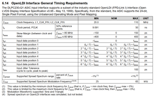
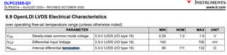
     we are using DLPC230S-Q1 for projector design. As we found in the datasheet of DLPC230S-Q1, there is an internal termination in it

but when we test the waveform, we found a wave reflection there.

Do we need any configuration to open the internal termination?

and we also found an option with the internal termination in DLPC230S-Q1's IBIS model

  • Hi Zhangyi,

    Thanks for using our forum! Please let my team and me look into this matter over the next two days.

    Regards,
    MIchael Ly

  • Hi Zhangyi,

    The DLPC230 does have a default ~100-ohm resistor for the OpenLDI interface like you have mentioned.

    You do not need to configure the resistor, as it is default.

    May I ask what kind of reflection you are seeing when you are measuring by any chance? I would also like to take a step back and ask how you are measuring the signal. Is it with a ground lead or with a tip-and-barrel method (AKA paperclip) method? Maybe differential probes?

    If a ground clip was used, it may be better to go with the other two methods listed above, as a ground clip makes a large inductance loop that causes ringing. There is a possibility the probe may have resistance as well. It is recommended you get a probe with minimal resistance for this case if you have not already done so.

    Here is an example of a large ground loop formed by a ground clip:

    and an example of the tip-and-barrel method that has a much smaller loop:

    If you do not have one of these available, you can actually make your own by tightly wrapping wire around your probe tip after removing the witch's hat, as shown below:

    Best regards,
    Michael Ly

  • Hi, Micheal 

       we use the differential probe to test the waveform。

       And we find that input of the DLPC230 from OpenLDI,it says it support spread spectrum,  

    Does it mean it can support PCLK with a spread spectrum? or it has a software option to open the spread spectrum option on DLPC230 

  • Hi Zhangyi,

    If you look at note (4) in the picture you sent, it says that the spread spectrum on OpenLDI interfaces was only simulated, not tested. That means that we cannot guarantee that it will work with an OpenLDI interface.

    On a different note, the datasheet says that TI has tested spread spectrum modulation at a maximum of 35 kHz and simulated up to 65 kHz. This is shown in Section 6.13. I am sorry if this section does not apply to you, as you were asking about OpenLDI.

    Regards,
    Michael Ly

  • Hi Michael 

       we get 2 models in the DLC230 IBIS model, ODT =1 and ODT=0, with the default config you said with DLPC230, there is  a default ~100-ohm resistor in it, and which model should we choose, ODT=1 or ODT=0?

  • Hi Zhangyi,

    I am sorry for the delay in response—many of us are getting back from a national holiday today.

    As for your question, I will have to consult the controller team to see if they can help me with this one. Please give me another 1-3 days to get back to you on this.

    Best regards,
    Michael Ly

  • Hi again Zhangyi,

    Here are the confirmed settings below:

    "fxlvrx020hh0l-odt0-rx:  internal 100 ohm terminations disabled

    fxlvrx020hh0l-odt1-rx:  internal 100 ohm terminations enabled


    We confirmed the settings now.


    Use ODT1 for simulation."