This thread has been locked.

If you have a related question, please click the "Ask a related question" button in the top right corner. The newly created question will be automatically linked to this question.

DLPC4422: How to repair the bootloader with UM232H

Part Number:
DLPC4422
DLP660TE

Hi Team,

Customer feedback: Issues in previous posts are not resolved. 

Previous posts is here:

https://e2e.ti.com/support/dlp-products-group/dlp/f/dlp-products-forum/1194173/faq-dlpc4422-how-to-repair-the-bootloader-with-um232h?tisearch=e2e-sitesearch&keymatch=%252525252520user%25252525253A507676#

New questions

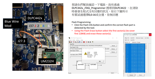
The file provided by Ti experts mentioned the Blue wire mod and would like you to help me check if the wiring is correct

I searched for DLPC4422 via DLPC442x_JTAG_Programmer

The program does not respond when cleared, as shown in the figure below, with attempts to select 0, 0:16, or all, and no response

Flash Programming:

• Click the Flash Info button and confirm the correct flash part is detected by the tool.

 Using the Flash Erase button select the first sector(s) (to cover first 128KB) and erase these sector(s).

Could you help?

Thanks & Regards,

Vivian

  • Hello Vivian,

    Thank you for reaching out with your question and including the images you've included. If I understand correctly, you are able to perform a 'Detect Chain' and it returns both '0' and '1' devices?

    The connections to the UM232H should be correct. Where is the jumper wire from UM232H.11 going? From this angle it looks like it isn't plugged into the J27.3 line.

    Please check the included 'FlashDeviceParameters.txt' file - this is a repository for the memory chips flash information we have utilized in the past.

    From the 'Flash Info' prompt you are seeing the Micron memory chip with 128Mb of flash. Please replace the active memory device by uncomment (removing '//') and bring the appropriate Micron memory to line 25 and comment out the old active memory (placing '//').

    After doing this, save the file and restart the JTAG Programmer GUI. This should help you appropriately be interfacing with the memory. You really only need to erase sector[0:15].

    Hopefully this was helpful!

    Best,

    Aaron

  • Hi Aaron,

    Thanks for your reply.

    Customer has further questions

    UM232H.11 and J27.3 are not connected
    I was able to execute the "detection chain"

    May I ask whether J31.1, J27.3 and UM232H.11 should be connected together?

    Finally, I have successfully erased sectors[0:15]. And then unplug the UM232H, turn on the switch(DLPC442x), the computer cannot receive the USB signal.

    Could you help?

    Thanks & Regards,

    Vivian

  • Hello Vivian,

    J31 - Bootloader jumper should not be attached to this system. I think you meant to say J37.1, in which case, yes; TRSTZ connects to UM232H.11.

    Please make this correction and follow the JTAG reprogramming guide - a blue-wire mod is required for reprogramming JTAG. The blue-wire mod removes connection on U22.4 and creates a connection on U22.1 - a single jumper wire from J27.3 (also U22.1) and J37.1 is not removing the connection to U22.4.

    Additionally, after making this fix, be sure to erase and reprogram both ASICs on your dual ASIC EVM board. We hope your UM232H Module is not damaged as we've noted in the the guide it can be damaged if the blue-wire mod is not followed.

    Hopefully this was helpful and you can get functionality back on your board!

    Best,

    Aaron

  • Hello Vivian,

    Please let us know if additional help is needed. I will be closing this thread on Monday. 

    Best,

    Aaron

  • Hi Aaron,

    There are no other issues with the customer at this time and you can close this post.

    Thanks for your help.

    Best regards,

    Jiahui