


Other Parts Discussed in Thread: DLPLCRC900DEVM, DLPC900, DLP6500FYE
The EVMs come in two models the DLPLCRC900EVM single controller board and the DLPLCRC900DEVM dual controller board. There are some similarities between the boards but sometimes pins, or devices on the EVMs may have different names so it will be beneficial to know which board you are debugging
The following are some helpful resources to get you started:
DLPC900 Datasheet: DLPC900 Digital Controller for Advanced Light Control datasheet (Rev. F) (ti.com)
DLPLCRC900EVM (Single Controller) User Guide: DLP® LightCrafter Single DLPC900 Evaluation Module (EVM) User Guide (Rev. C)
DLPLCRC900DEVM (Dual Controller) User Guide: DLP LightCrafter Dual DLPC900 Evaluation Module (EVM) User's Guide (Rev. B)
DLPC900 Programmer Guide: DLPC900 Programmer Guide (Rev. H) (ti.com)
1. DLPLCRC900EVM/DLPLCRC900DEVM: The board is not turning on; where to start debugging?
When debugging the DLPLCRC900EVM, it is important to check the most common and general issues first and work your way down to more complex and specific issues to narrow down the problem.
Check Power connector and any derivative voltages
- Check Power connector: For the DLPLCRC900EVM (single controller), the power connector can be observed at J17, whereas the power connector for the DLPLCRC900DEVM (dual controller) can be observed at J20. Make sure that a 12V power supply is connected to the corresponding power connector jumper.
|
|
Single Controller EVM |
Dual Controller EVM |
|
Power Connector |
J17 |
J20 |
- Verify derivative voltage values: Use a multimeter to check the derivative voltages and ensure that they meet the expected values. Refer to the schematic and the expected voltages in the datasheet for guidance.
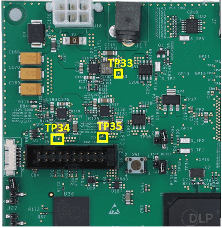
To check the derivative voltages, use a multimeter to probe the test points and verify that the voltages match the expected values. The schematic of the single controller EVM and the schematic of the dual controller EVM provide helpful information for checking the power supplies. Below is a table of voltages and their corresponding test points.
|
Single Controller EVM |
|
|
Expected Voltage Output |
Testpoint |
|
1.15 V |
TP33 |
|
1.8 V |
TP34 |
|
3.3 V |
TP35 |
|
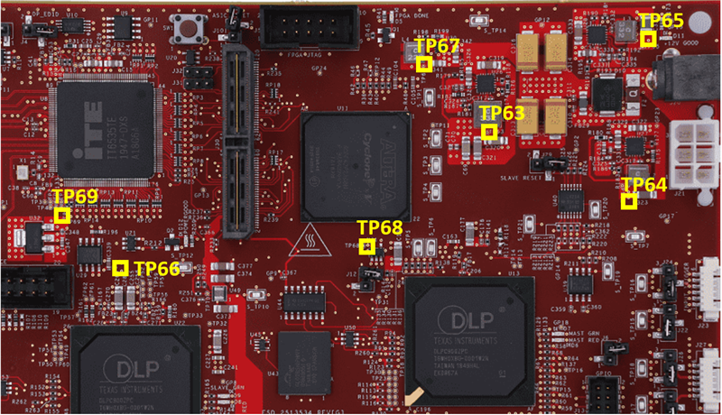
Dual Controller EVM |
|
|
Expected Voltage Output |
Testpoint |
|
1.12 V |
TP63 |
|
1.8 V |
TP64 |
|
3.3 V |
TP65 |
|
1.8 V (for controller 1.8 V analog) |
TP66 |
|
3.0 V (for FPGA VCCIO) |
TP67 |
|
2.5 V (for FPGA AUX/PLL power) |
TP68 |
|
1.8 V (for HDMI RX 1.8 V analog) |
TP69 |
Related E2E topics:
DLPC900: does not boot up properly - DLP products forum - DLP®︎ products - TI E2E support forums
After turning the power supply on, do LEDs turn green after startup?
Both DLPC900 EVMs have LED indicators that help indicate the states of different parts of the boards, such as the controllers and FPGAs. The connectors and indicators can be found in section 5.5 of the single controller user’s guide and section 1.5 of the dual controller user’s guide. The LEDs are as follows:
|
|
Configuration and Power LEDs |
Heartbeat LEDs |
|
Single Controller |
D8, D9 |
D6 |
|
Dual Controller |
D5, D11, D12 |
D7,D9 |
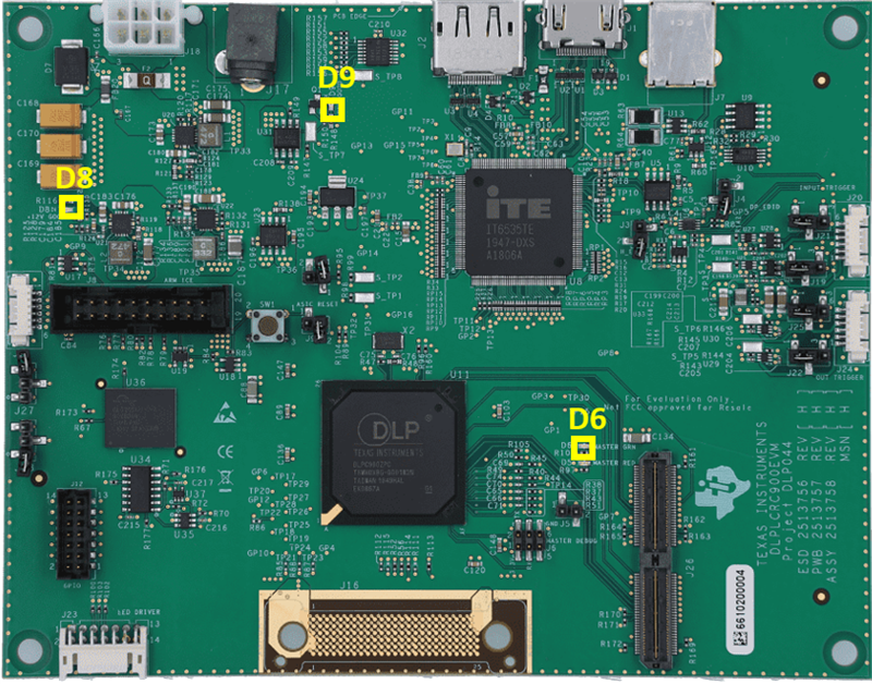
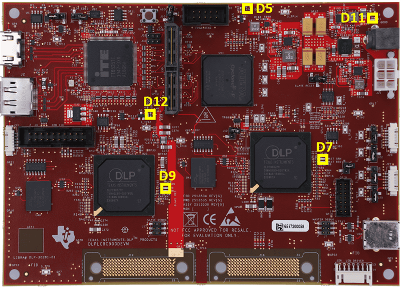
Configuration and Power LEDs: These LEDs correspond to the 12V power supply on both single and dual controller EVMS, and the dual controller has extra LED for the FPGA configuration as well
Heartbeat LEDs: These LEDs correspond to the controllers on the EVM and indicate that the controllers are operating correctly
If you do not see these LEDs on power up, then this means that the issue is related to what the LEDs are supposed to correspond to. For power related issues you want to check the power supplies and configuration of jumpers and ensure they follow the correct configuration as described in the user’s guide. For FPGA configuration and heartbeat LED issues, it is helpful to reprogram the flash on the FPGA through the GUI software following the instructions in section 7.9 of the single controller EVM user’s guide and section 3.9 of the dual controller EVM user’s guide.
After getting a successful power up is the DMD cycling through prestored patterns?
Once a successful power up is achieved and the corresponding LEDs turn green, you should see the DMD cycle through prestored patterns after 5 seconds. If you do not see the DMD displaying patterns, the issue could be related to the connections of the flex cables between the controller board or improper DMD voltages.
- Check the cable connections following the sections given below
- Single Controller: EVM User’s Guide Section 5.7
- Dual Controller: EVM User’s Guide Section 1.7
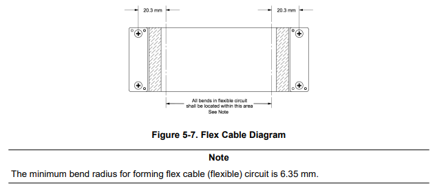
- Ensure that the flex cable does not have any missing C-springs. If any of the C-springs are missing or if the connection is loose, it could cause the DMD to act abnormally.
- You should also check the voltages on the DMD and ensure they are in the expected ranges using a multimeter
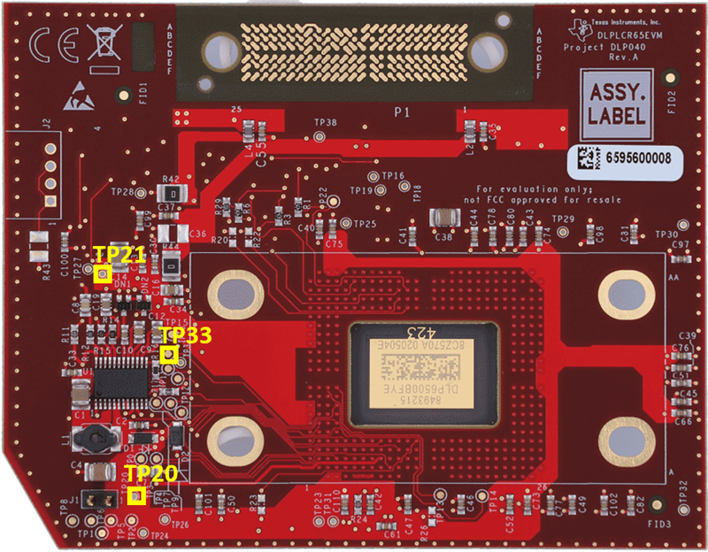
- From the DMD EVM product page, download the schematic for your respective DMD EVM and search for Vbias, Vreset, and Voffset. The schematic will show the testpoint you will need to probe with the multimeter.
Example (DLP6500FYE):
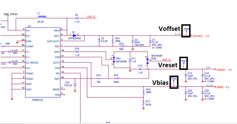
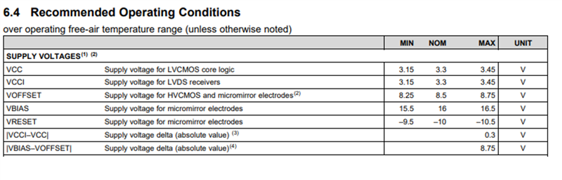
- Then download the DMD datasheet from the DMD product page and the datasheet will have the expected ranges for the Vbias, Vreset, and Voffset. If the values are not within the expected range the DMD will no function properly.
Example (DLP6500FYE):
Related E2E Topics:
2. Differences between modes
The different operating modes of the controllers can be found in section 7.3.1 of the single controller EVM user’s guide and section 7.3.1 of the dual controller EVM user’s guide.
The EVM can be commanded to enter one of four operating modes. Within the Operating Mode group box there are four choices:
- Video Mode: This mode is primarily used for display applications, and is not recommended for applications which require pixel and timing accuracy. In this mode, the user can choose from the four following video modes:
- Parallel RGB interface
- Internal test pattern generator with ten test pattern options
- Pattern image display from flash memory
- Solid Curtain with choice of color
- Pre-stored Pattern Mode: In this mode, the user can create a pattern sequence using the images stored in flash.
- Video Pattern Mode: In this mode, the user can define a pattern sequence using pattern data or video streamed using a parallel RGB interface
- Pattern On-The-Fly Mode: In this mode, the user can create a pattern sequence using bitmap images that are loaded into the internal memory of the DLPC900 via USB or I2C interfaces. This mode can be helpful to view a pattern sequence before storing the images in flash memory, as updating the flash to use Pattern Mode can be a timely process.
Related E2E Topics:
3. GUI issues
The GUI will typically indicate error messages that can be useful for debugging issues You can find each of these error-related flags in section 7.3.4 of the single controller EVM user’s guide and section 7.3.4 of the dual controller EVM user’s guide. Some of the error-related flags are listed below:
- Any status flags?
- Sequencer Error
- This typically occurs with any of the pattern modes when preparing a pattern sequence and the timing of reading the status. This is commonly the result of choosing exposure times that are too short or too long.
- Forced Swap Error
- The box is checked whenever a forced buffer swap occurs. This error can occur if the DLP LightCrafter Single DLPC900 EVM is set to Video Mode, and the vertical back-porch timing is too small. The error can also occur if the DLP LightCrafter Single DLPC900 EVM is set to Video Pattern Mode, where the patterns are from the video port and the pattern sequence timings do not match the video port VSYNC; specifically, the cumulative exposure times are greater than the frame time. Forced buffer swaps may also occur during any pattern mode when preparing a pattern sequence and the timing of a status read. The user may need to perform additional reads of the status to obtain the correct state of this indicator. If the box continues to be checked, check for an error condition in the pattern sequence.
- Check for jitter on the Vsync signal and also check that your input parameters, such as back porch and clock signals, are as expected and do not have noise. In addition, we check that when internal/test patterns are selected, a forced swap error does not appear.
- The Forced Buffer Swap error remains until a reset is performed.
- Controller *Firmware* and DMD Incompatible
- This error can be caused by power blips, which can result on corrupted firmware. Refer to JTAG Flash section 7.11 of the single controller user’s guide or section 3.11 of the dual controller EVM user’s guide for instructions on dealing with corrupted firmware or a blank board.
- This error can also be caused by touching the controller board in the wrong places, which can lead to issues with the DMDs, particularly the DLP6500
- Sequencer Error
4. What is the proper shutdown process?
It is Recommended standby mode be used for all revision "B" DMDs and later, as power standby is needed to properly park the DMD.
