This thread has been locked.

If you have a related question, please click the "Ask a related question" button in the top right corner. The newly created question will be automatically linked to this question.

DLP3030Q1EVM: about DLP3030Q1 EVE not workable

Part Number: DLP3030Q1EVM

Hi,

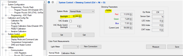
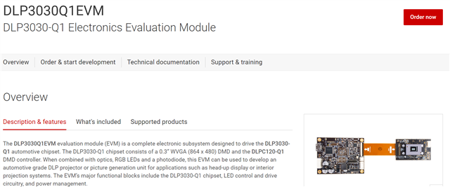
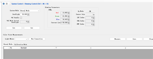
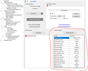
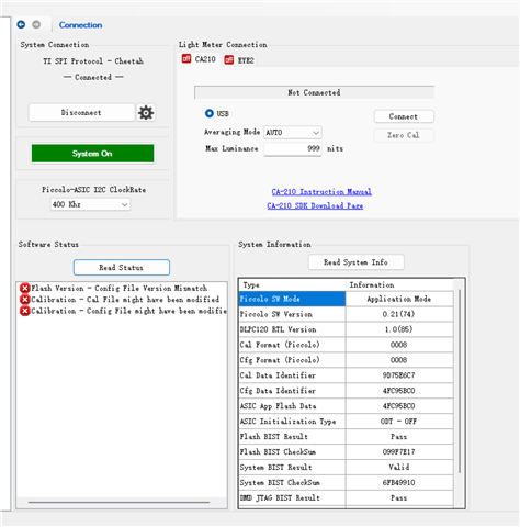
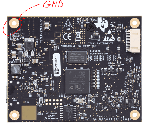
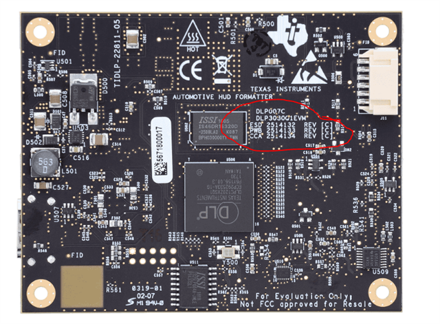
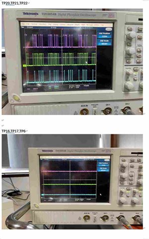
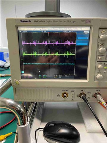
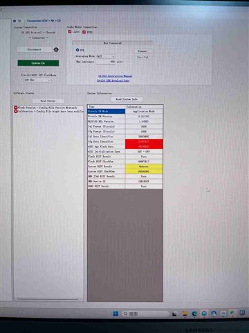
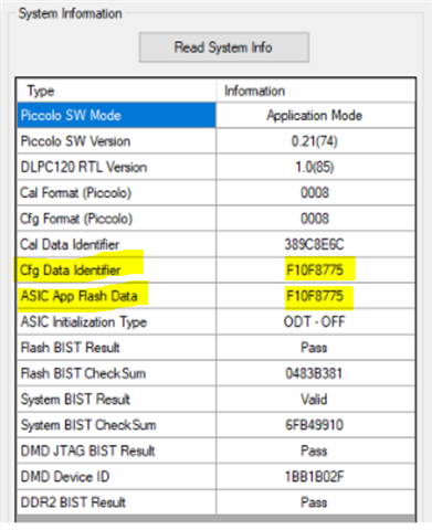
We have bought 2 sets of DLP3030Q1EVM, and connected all parts, including DMD board, R\G\B LED and PC, according to the User Guide. We can see the image from the DMD chip and get the data from the EVM through the ACP.  Unfortunately the R\G\B LED are not workable. We made some testing and found there are no driving current and volume at the output terminal
We are looking forward to your supporting.
Thanks!
  • Hello User,

    Welcome to the E2E forums and we hope to assist you with your questions. 

    Please see the following debug questions to help us better understand the situation.

    1. Did you try both EVM and neither of them are working? Have you modified or changed the software in any way with either of the systems?

    2. What power supply voltage and current rating are you using?

    3. Where are you measuring current and voltage? Do you see no current draw from your power supply?

    4. One common issue is the backlight (brightness setting) may default to zero on power up.

    Please go to this page in the ACP and ensure the backlight value is non zero and press "set". You can also see if the PWM values are non zero. 

    5. Do you have a picture of your setup and wiring? Our EVM kit normally does not come with LEDs only the formatter board, dmd board, and cables. What LEDs are you using?

    Regards,

    Alex Chan

  • Hi Mr.Chen,

    Thank you for your feedback. The answer to your question is as follows:

    1. Both of EVM boards are not workable and we did not make any modification and change to the software of the boards.

    2. The supply power voltage and current is 12V and 5A respectively.

    3. The driving current and voltage are measured at "LED POWER CONNECTOR" on the EVM board. 

    4. The backlight value and PWM value are shown in the picture as follow. 

    5. LEDs we used are purchased from OSRAM, Q8WP.

  • Hello User,

    Thank you for your responses. I have a few additional questions.

    1. Were both of these DLP3030Q1EVMs purchased together recently? I assume you don't have any older DLP3030Q1EVM that works or was purchased in the past?

    2. So you are testing with just an individual LED connected without an optical engine or are you using an optical engine with the LEDs?

    3. Do you have a picture of your setup? Do you have access to an oscilloscope?

    4. Can you provide the following screen from your DLPC120 ACP for more information?

    Regards,

    Alex Chan

  • HI Mr.Chen,

    Thank you for your reply. We purchased two sets of DLP3030Q1EVM last month and don't have any oled DLP3030Q1EVM in the psst. We did test with one LED, with three LEDs and with an optical engine with LEDs respectively. The results are same. Please let us know if you have any proposal for further testing.

    attached you will find a picture from DLPC120ACP.

    best regards,

    Yu Dong

  • Hello, 

    Do you have access to an oscilloscope? Please go to the following page and you can use the schematic and assembly drawing of the formatter board to help figure out where these test points are.

    https://www.ti.com/tool/TIDA-080004#design-products

    You can use these connectors as a ground plane for probes.

    Can you probe the following signals and provide waveform captures?

    1. TP6 photodiode feedback signal

    2. R_EN, G_EN, B_EN which are Tp20, TP21, and TP22

    3. TP17 CNTRL_OUT

    4. OC_COMPOUTZ TP16

    Also what rev number are the boards you have, are they rev c?

    Regards,

    Alex Chan

  • Hi,

    As your request we probed the signals of TP20,TP21,TP22,TP6,TP16 and TP17. There is a 3.3V output in TP20,TP21 and TP22 respectively, and zero output in TP16,TP17, and TP6. I have captured the pictures of waveform, but I can't paste the pictures on this board. Please let me know how to do it. 

    The number on the board is REV C.

    Best Regards,

    Yu Dong

  • Hi Chen,

    I pasted the picture of waveform for your reference.

    Best Regards,

    Yu Dong

  • Hello Yu Dong,

    Thank you for all that debug information that is very helpful in narrowing down the problem. It looks to be a hardware issue with the board. Was all this tested with the optical engine connected? Are you able to see the same waveform behavior on your second board as well?

    Could you also perform the following measurements.

    1. Can you measure TP24 and provide a waveform.

    2. Can you measure the voltage across R9 sense resistor and provide a waveform.

    3. Can you measure TP7 OC_FB signal and provide a waveform.

    Regards,

    Alex Chan

  • Hello Mr.Chen,

    We made the test with optical engine connected. There is a 2V signal voltage at TP24, 2V voltage across R9, and 3.3V signal voltage at TP7. The waveform is shown as the picture above. Red is the waveform of TP24, green is R9, and blue is TP7.

    Best Regards,

    Yu Dong

  • Hello Yu Dong,

    We believe the issue may be a manufacturing issue where the wrong resistor was used for R9. A 20 megaohm resistor may have been wrongly installed instead of a 20 milliohm resistor. 

    Are you able to measure the resistance of R9 using a multimeter when the system is powered off? 

    Would you happen to have any replacement parts of the R9 (TT Electronics/Welwyn LRF2512-R020FW) to install a new R9 onto the board or have similar sized resistor to try out?

    The alternate method would be to submit an RMA. 

    Regards,

    Alex Chan

  • Hello Mr.Chen,

    We replaced the R9 on both of EVM boards with a new 0.02ohm resistor and one of the EVM is workable normally. Another EVM is still not workable. We found the system information(attached) is not same as EVM that is workable.   Maybe we did some modification to the software unconsciously.

    Thank you so much for your support and looking forward to your further help.

    Best Regards,

    Yu Dong

  • Hi Yu Dong,

    Glad to hear that the change for R9 to one of the boards is working. 

    For the other board that is not working it looks like the configuration file is different between the one programmed into the piccolo MCU and the ASIC application flash used by the DLPC120. These need to match such as below:

    Do you have access to the following page on mysecure? We have a standard configuration file and calibration file that you can try programming onto your EVM for both the piccolo MCU and the asic application flash. 

    You can see the programming steps in section 5 of the Automotive Control Program User Guide I am linking below. You would only need to perform steps 5.3 and 5.4. 

    1106.DLPU059_ACP_UsersGuide_March2018 (2).pdf

    Regards,

    Alex Chan

  • Hello Mr.Chen,

    The other EVM board can also work in nomal after programming onto the piccolo MCU and the asic application flash according to your guidance. Thank you for your patient support and help.

    Best Regards,

    Yu Dong

  • Hi Yu Dong,

    Glad to hear both systems are now working. I will close this ticket out. 

    Thanks,

    Alex Chan