Other Parts Discussed in Thread: DLP3030-Q1, DLP5534-Q1, DLP9000
Hello
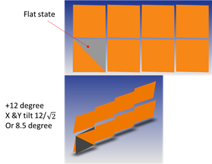
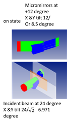
- What is the fill factor for DLP651NE not reported in data sheet
- Can someone explain how could possibly the on-state ray tracing of mirrors, considering100% reflective lead to fill factor above even 89%. read this application form: https://www.ti.com/lit/ds/symlink/dlp9000.pdf?ts=1694427507345&ref_url=https%253A%252F%252Fwww.ti.com%252Fproduct%252FDLP9000 page 31 and application note: https://www.ti.com/lit/an/dlpa083b/dlpa083b.pdf?ts=1694384680206&ref_url=https%253A%252F%252Fwww.google.com%252F page 2 for onstate fill factor. I am using zemax. this is to adjust the gap between mirrors to get the proper fill factor. or someone please share the gap between the micro mirror arrays in flat state. no matter what you do the fill factor do not go above 90%. the only way to get fill factors of above 90% si to have mirror flat facing incident beam and then adjust the gap to get to whatever fill factor Ti reports. not to mention TI reports for example open etime 94% and one time 90% for DLP 9000. It is a mess in reporting correct values.
- what is the thickness of glass used in DLP651NE
- what is the distance of back of glass to top of mirror arrays
- can someone explain how could possibly the on-state
Thank you whoever response to this