This thread has been locked.

If you have a related question, please click the "Ask a related question" button in the top right corner. The newly created question will be automatically linked to this question.

DLPDLCR3010EVM-G2: or DLP3010EVM-LC? - Suitability for stable static imaging

Part Number: DLPDLCR3010EVM-G2
Other Parts Discussed in Thread: DLP3010EVM-LC

Hi,

We are looking for a DMD for to project a static, stable pattern using a single colour in the visible (could be broadband or monochromatic). We want to capture the resulting illumination with very short exposure times (on the order of 10s of microseconds) in a repeatable manner, so stability in the illumination is very important. 

We are currently using the DLPDLCR3010EVM-G2, and in an answer to an earlier question that we posted, we can achieve single colour illumination by turning off two of the LEDs. We tried to do this by turning off the blue and green LEDs, but when observing the light intensity on an oscilloscope (see figure 1 below) we realised that

(1) this configuration doesn't let us keep the red LED on throughout (i.e. when we turn off the blue and green LEDs, this just means the DMD does not project any light during their scheduled parts of the cycle). This does not work for us as the signal capture could occur during the times that no light is being projected. 

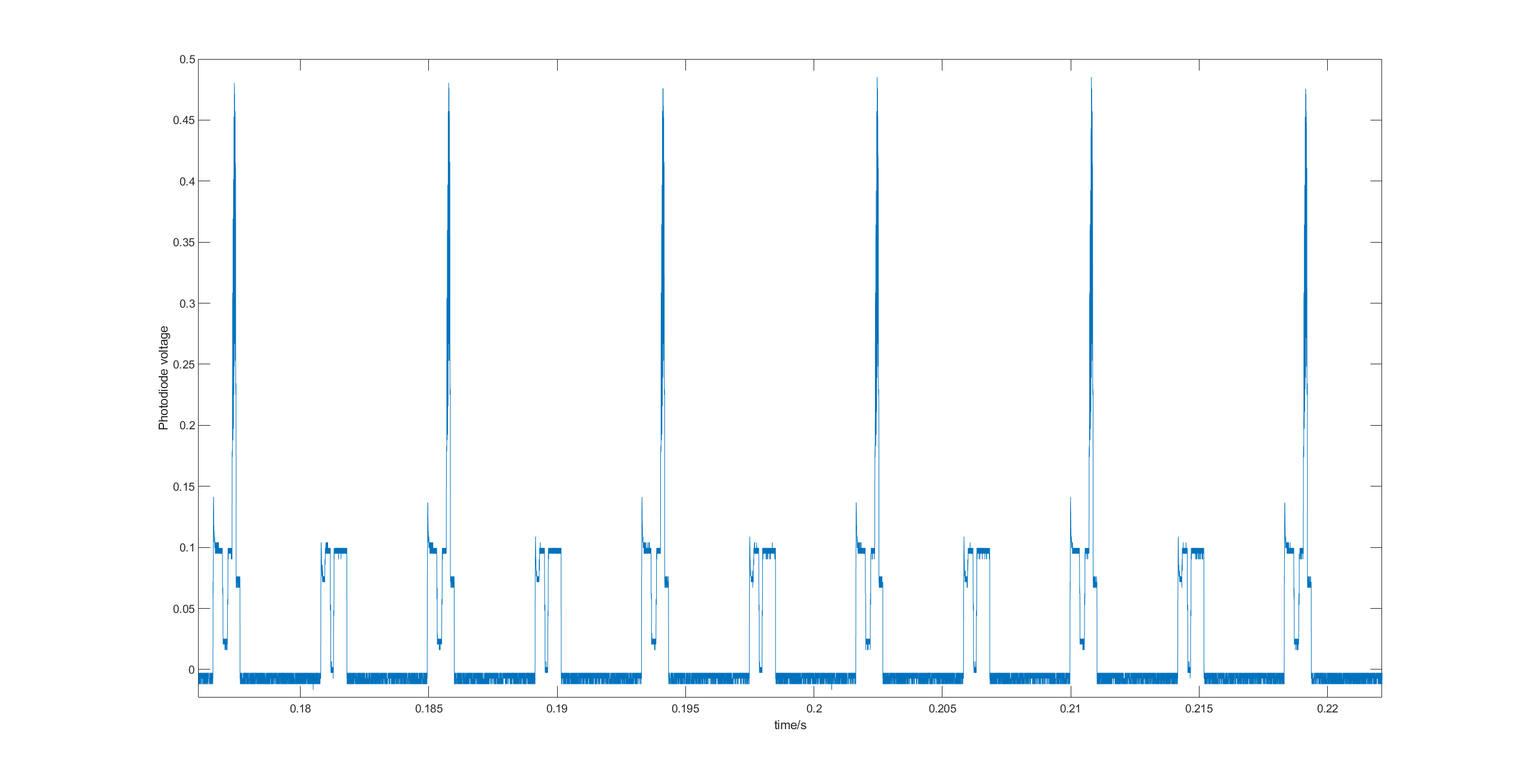
(2) when the red LED is on, there is a sharp peak with varying intensities that occurs, which affects the repeatability of the collected signal. When we zoom in on the cycles, we see that there seems to be alternating cycles as well. Figure 2 shows this with all LEDs on, but the same is seen when only one LED is on.

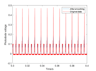
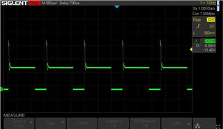
Figure 1: Oscilloscope data showing the 240Hz signal 

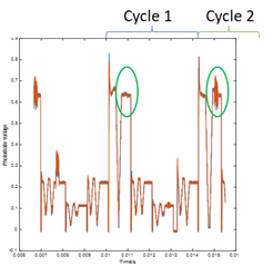
Figure 2: Zoom in when all three LEDs are on, showing two distinct cycles

Given our requirements for illumination stability and single colour illumination, is there anything further we can do with the DLPDLCR3010EVM-G2? Alternatively, would moving to the DLP3010EVM-LC or any other product be more suitable for our application?

Thanks! 

Kind Regards

Yuchen

  • Hello Yuchen,

    I believe the DLP3010EVM-LC would be much better for your use case. The DLP3010EVM-LC has light control modes which allow you more control how the patterns are displayed, the illumination times, pattern bit depth and monochrome/rgb. Please see Light Control Commands in the DLPC3478 Software Programmer's Guide for more details of what you can control. Please note while you have more control of the illumination timings, some dark time is required. 

    As for your second concern, do you see this when there is only one led driven? 

    Best,

    Maximus

  • Hi Maximus,

    1) Here is an image of a constant pattern with only the red LED on. Not only can two cycles can still be seen, but the shape of the cycle also differs from the previous one above with all LEDs on as well. Any idea what the spikes and the two cycles are caused by?

    2) Just to clarify, with the DLP3010EVM-LC, if I were to set monochromatic illumination using the light control tab in the GUI, would I expect to see something like this: 

    + some noise? I.e. the only changes in the signal are due to noise (from detector and LED) and the dark time of the DMD, and maybe a small amount of stray light (see q4)? Would there also, for example, be the spikes and cycles that we observed in Q1?  

    3) What is the minimum dark time of the DMD? 


    4) I noted from this other forum post that there may be some stray light from the off-state DMD pixels, would you be able to advise on the magnitude of this stray light in the native DLP3010EVM-LC without any modifications?

    Kind Regards

    Yuchen

  • Hi Yuchen,

    1) I am still looking into what would cause such a large spike especially every other cycle. Please give me some time if you still want the answer to that. 

    2) Below is a screenshot of what my photodetector captures using the DLP3010LC-evm in red pattern mode. As you can see it is very consistent each cycle, the rise in the beginning is due to in rush current as the LED first turns on. The timings used in this example are Pre-Exposure dark time: 250us, Exposure time: 1000us, and Post-Exposure dark time: 60us.

    3) Our most up to date firmware release notes (link) have more details as to the minimum dark time. Typically the minimum total dark time ( pre + post) is 202 us. 

    4) To measure this I would suggest projecting a blank or black pattern and measuring the output to see how much stray light you can record when all the mirrors are in the off state.

    Best,

    Maximus