This thread has been locked.

If you have a related question, please click the "Ask a related question" button in the top right corner. The newly created question will be automatically linked to this question.

DLPC900: can not connected to GUI-5.2.0

Part Number: DLPC900
Other Parts Discussed in Thread: DLP5500, , DLPLCRC900EVM

 DLPC900 is assembled with  DLP5500 in my system. It has been running  successfully for the past few months. But the day before yesterday, the PC suddenly couldn’t connect to it. 

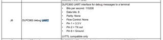
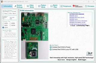
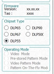
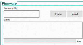
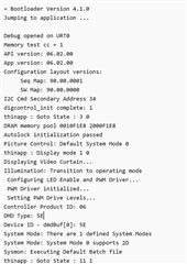
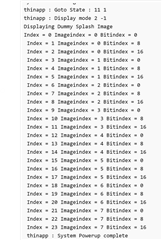
The specific situation now is that after powering on, D8 and D9 on the DLPC900 light up green normally, D6 also flashes alternately normally, and DMD also displays the prestored pattern normally. But the DLPC900 GUI -5.2.0  can not connected. System Controls shows disconnected and Firmware shows 'xxxxxxxxx'. 

Is there any way to solve this problem? If necessary, I can provide photos or videos. Thanks in advance.

  • Hi ,

    Are you using a Microsoft Windows machine? May you check to see if you see it in your device driver, if so?

    Have you attempted using another known-good USB cable? I just want to check the basics first.

    Regards,
    Michael Ly

  • Hello Michael,

    Thanks for your response.

    The pc is Microsoft Windows machine and I don't find it in the device driver.  I have another DLPC900 assembled with DLP6500 and it can be connected to the GUI. I swapped the cable of these two sets of devices, the 6500EVM can still be connected, while the 5500 still can't be connected. 

    I used to plug and unplug the USB cables frequently to alternately upload pattern to the two DMDs with one pc ( as if one pc can only connect one DMD). I don't know if this operation will have a bad effect on DLPC900.

    Regards,

    Yu

  • Hi Yu,

    Thanks for your detailed procedure. This helps clear some questions out of the way.

    May I get a screenshot of what your GUI looks like when you are using the DLP5500 EVM board? I have never hot-swapped the USB for this sort of application, but I am unsure how the hardware will be affected if you do that? If anything, it may confuse the GUI you are using.

    What status flags are you seeing on the DLP5500? I would like a screenshot of your entire window of the GUI, if possible.

    It would also be helpful to understand and see any error windows that come up so I can trace this.

    One of the best ways is to use the UART port on your DLPC900 board to get the debug log. This is located at J6. More information can be found in the DLPLCRC900EVM's single-ASIC user's manual under section 5.5.

    Let's first do the highlighted actions before we move onto more time-consuming and complicated solutions, however.

    Edit:

    Please only have one  instance of the GUI running at a time, and start a new instance when you swap DMDs. Let's isolate everything one at a time until we come to a solution.

    Thank you,
    Michael Ly

  • Hello Michael,

    Thanks for your help.

    As you can see in the picture, the GUI cannot detect DLP5500 and no error windows appear. And the PC Device Manager_Universal Serial Bus controllers also do not show the USB driver. So I believe that there might be something wrong with the Host USB interface (J7) or related  electronic components (such as U13? I‘m not sure).

    Regards,

    Yu

  • Hi Yu,

    Let's try the following:

    1. Install a jumper to J11 BOOTHOLD. This puts the system into its bootloader mode. Please ensure the system is fully powered off and not receiving power before installation.
      1. Connect the controller board to the host computer and power the system on with a 12 V, 5 A power supply
      2. Close all instances of GUI and open a new instance
      3. If system comes up in standby and recognizes a DLPC900 plugged in, please select correct DMD type, as the GUI will not be able to determine DMD type while in bootloader mode. If this does not work, move to option #2 below.
      4. Go to firmware page click 'Browse..."and locate the firmware (*.img) file for the DLP5500. This is typically located under "C:\Texas Instruments-DLP\\DLPR900PROM-x.x.x" for Microsoft Windows machines, where "x.x.x" is just the firmware version.

      5. Open the *OOB.img firmware file for your DMD and then click "Upload" and wait until flashing and verification complete.
      6. When complete, the GUI will let you know programming was successful in the status bar:
    2. If USB does not work even under bootloader mode, please power off your system/disconnect power. We will attempt to use the UART debug log to see what is happening instead.
      1. Remove the jumper from J11 BOOTHOLD jumper.
      2. Connect a UART device to J6:
      3. You may use a terminal emulator such as TeraTerm.
      4. Use a Baudrate of 115200
      5. Please let me know results if you must perform this
    3. You may also follow the guidelines in Section 7.11 of the user's guide to reprogram the bootloader. USB communication does not work if the bootloader is corrupted.

    Regards,
    Michael Ly

  • Hello Michael,

    The first method doesn't work. It still doesn't connect. Then pic 1&2 are the output of the debug log. Thanks for your help.

    Regards,

    Yu

  • Hi Yu,

    May I get some additional context?

    1. Have you ever been able to reprogram the firmware on the DLPC900 + DLP5500 system? What were you doing before USB communication stopped working? Was it in the middle of your work, or after you had come back and powered on the device?
    2. Let's see if the debug log tells us anything when you plug a USB in.
      1. When you plug in the USB, please have your UART Debugger active. The USB communication is controlled via software in the bootloader. Please check if the UART debugger picks up any debug messages about USB. If it does not, something is likely wrong with the bootloader.
    3. Are you using any interface between USB and host computer such as a USB hub? If so, please directly connect the controller to the PC with USB.
    4. Are you able to communicate with the DLP5500 on your other DLPC900 board that has the DLP6500? We will give you a replacement board if this damages your existing one. If this working board is required for other research or application at the moment, let's hold off on that and move to step 5.
    5. You can reprogram the bootloader using the UM232H above, and I would recommend having one of these along with a wire harness that can connect to the DLPC900 in case any of your DLPC900 boards ever get a corrupted bootloader.
      1. The wire harness will need the following connector and crimp. The information can be found in the user's guide for DLPLCRC900EVM.
    6. If the above does not work, I would like to schedule a video call with you so we can avoid back and forth messages in different time zones. A single call or two may be much faster. I will send you a friend request just in case.

    Thank you,
    Michael Ly

  • Hello Michael,

    I didn't reprogramm the firmware and before USB communication stopped working, I was swapping DLPC cables that connected to the PC. And it was in the middle of my work.

    The debug log doesn't send anything when I plug in the USB.

    And I tested two of my DLPC900 boards last week, specifically the single of TP16 as shown in the picture. When I plugged the USB in, the working board detected a 3.3V signal, but the broken broad did not. So I think it's probably a hardware problem.

    In addition, I would like to ask why R63 and R64 resistors need to use 3/4W power,empirically speaking, 1/8W  (0603 footprint ) or even 1/16W  (0402 footprint ) is enough.

    Btw, if the hardware is really broken, will you provide repair service?

    Thanks,

    Yu

  • Hi Yu,

    Have you tried the same UART debug log on your working board? What does the log say when you plug in USB, if anything at all? Please provide a screenshot. This may help me in determining what happens when a USB is first plugged into the board and how the bootloader handles this.

    I was swapping DLPC cables that connected to the PC. And it was in the middle of my work.

    May I ask how you were handling the board when connecting and disconnecting USB Were you touching the board in any way? Did you have some form of ESD protection?

    Please note that, although it is fine to hot-plug your USB, you must be careful because the electronics are exposed. Are you touching the board in any way as you plug the USB cable in? Are you using an ESD-safe environment with an ESD table or surface for your board? Are you grounded via a tested wrist or heel strap?

    I would be very careful in hot-plugging your USB if you are touching the board with no ESD protection otherwise. The board, without an enclosure, is still an ESD-sensitive device.

    One more question: Have you tested the buffer, U12, to see if the output enable is ever being pulled low? You will not get an output at TP16 until that line is pulled low. Please be very careful when probing to avoid shorting pins 1 and 2 together with your probe.

    In addition, I would like to ask why R63 and R64 resistors need to use 3/4W power,empirically speaking, 1/8W  (0603 footprint ) or even 1/16W  (0402 footprint ) is enough.

    I am sorry, but I do not know the answer to this question. I can see if someone else in the office might know or has seen something similar, though. I found the input high and low voltages  and currents and found that USB has a max of 56 mW power. If we look at the rest of the schematic, we see lots of information for each other resistor such as its tolerance. This 22 ohm, 3/4 W resistor was likely just the part we used because it was one of the first parts we saw. You may use other resistors.

    Regards,
    Michael Ly

  • Hi Yu,

    I am marking this thread as resolved because you were able to get a new board and we talked offline about this.

    To summarize what had happened, your new board would not show anything on your DLP5500 DMD, but it would connect to the GUI, and you saw firmware related to DLP6500.

    You then reprogrammed this with (what I assume to be the *OOB.img) firmware file, and it works now. Other users unfamiliar with this process may refer to Section 7.9.2 in the DLPLCRC900EVM User's Guide in the future. A DMD does not need to be attached to the controller board for  this particular process because the BOOTHOLD jumper will be installed. The user may choose to do this with or without the DMD.

    Do you have any other questions, Yu? If not, please consider marking this post as a resolution to your issue.

    Thank you,
    Michael Ly