This thread has been locked.

If you have a related question, please click the "Ask a related question" button in the top right corner. The newly created question will be automatically linked to this question.

DLP5530S-Q1: RGB LED connection

Part Number: DLP5530S-Q1
Other Parts Discussed in Thread: DLP5530PGUQ1EVM

We are developing AR HUD using DLP5530. 

There is an issue regarding brightness. So our optic engineer change the LED to Osram Q7WP that has 2 LED chip in a LED package like the picture below.

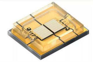
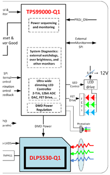
And Each R, G and Blue LEDs are connected as series like picture below. 

I'd like to know this way is right way to improve brightness and if it is right, could you provide reference schematic for this way? 

  • Hello Jin Cho,

    What system are you using?  The Q7WP connects to the DLP electronics in the same way (anode / cathode) as the Q8WP LED that is included in the DLP5530PGUQ1EVM.

    The question of brightness is complicated.  The Q7WP is twice as much LED as compared to the Q8WP LED.  However, the optical systems to couple the light from the LED to the DMD, would have to be completely redesigned to increase the brightness.  If you just changed the LED, but the optical design is the same as the Q8WP LED, then the brightness will not increase much because the light will not get coupled to the DMD.

    We would need to understand much more completely the system and details about what you are doing.  

    Please explain more about your system - optics, mechanics, and the electronics.

    Thanks,

    Jason

  • Our system is AR HUD. Currently optic design is going to be changed.

    And we are using your EVB DLP5530PGUQ1EVM .

    I have just question if we use Q7WP LED and each LED connection is series, which point need to be changed in your reference design.

    Could you let us know change point in schematic in your reference design?

    BR

    Jin

  • Hello Jin,

    We do not think that you need to change anything in the design.  You do have to make sure not to lower the voltage for the LED driver since the two LEDs are in series.

    Fizix

  • TO add to Fizix comments, the LED Driver high side should be 1V + LED Vf (2x).  The 1V is for margin.  Roughly, speaking the min voltage to the LED driver high side should be 7V.