DLPC4430EVM: Connection Issue

Part Number: DLPC4430EVM
Other Parts Discussed in Thread: DLPC4430, DLPA100, 4430

Tool/software:

Hi Team,

Can you help us guide our customer for an HDMI input connection to the DLPC4430EVM?

They also encountered a connection issue with the EVM when using with the GUI. Their issues are summarized on the attached powerpoint.

PS: EVM is still within warranty. Thanks in advance!


Kind Regards,

Jejomar

DLPC4430EVM Issue.pptx

  • Hello Jejomar,

    Please see my feedback below:

    1. HDMI connection: they don't need extra cable. Just connect J2 on the formatter board with J500 on the front end IT6802 board. There is a HDMI port on the front end board.

    2. Connection between EVM and GUI:

    • Please note that the Figure 2-2 ON/OFF switch in the DLPC4430EVM user's guide is not matching the released EVM on TI.com. The correct ON/OFF state should opposite of the figure. In other words, up side is ON, down side is OFF. 
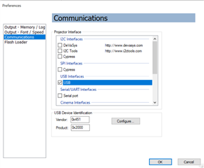
    • Please make sure the communication setting in the GUI is USB. 
    • Following the instructions in the section 2.2.3 of the DLPC4430EVM user's guide for re-programming the EVM. 

    Regards,

    Lori 

  • Hello Lori,

    Thank you for looking into this. I followed this up with the customer and it seems that they are still facing the issue.

    Attached is their EVM configuration. First page is the GUI error message and second page is the connection.

    connection.pptx

    Kind Regards

    Jejomar

  • Jejomar,

    I believe their picture shows SW1 in the OFF position; have they tried both positions?

    In booth hold mode (J8 in place), they should be able to communicate with the boot loader and program the flash with or without a DMD or Front-end (It6802) board present.  SW1 must be in the ON/RUN position.

    In normal mode/not in boot hold (J8 removed), both the DMD board and the Front-end IT6802 board must be present, otherwise the embedded software will not The EVM kit will not complete initialization and will not communicate.  An IT6802 board should have included in the EVM kit.  As Lori mentioned, they need to plug the IT6802 card into J500 on the DLPC4430 formatter board.  

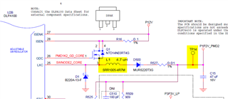
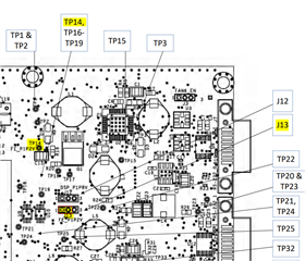
    In the previous message, the attachment shows a crack on L1.  I would not generally expect a crack to cause a problem.   Looking at the schematic, L1 is the inductor used to create the 1.2V supply for some front-end boards; this supply is not used by the IT6802 board (P1P1V should be selected by default, J13 Pins 1&2 connected).  So, I would not expect this to be a problem unless there is a short or other issue causing that DLPA100 to have problems.


    If you want to check that supply, it has a test point TP14.

    My first suggestion would be to try SW1 in both positions.  Also try with the IT6802 board present.

    You could also check the debug serial port output on J7 and J16 to see if the boot loader and/or embedded software are starting.  I am not sure which port is used in these builds; the boot loader debug may output on a different one than the running software -- I am not sure.  Configuration is 115200/8/N/1.  

    Regards,

    Gary

  • Hello Gary,

    Thank you for the detailed guidance. I followed this up with the customer but unfortunately they are still encountering connection issues.

    Their set-up are detailed on the attached powerpoint.


    Kind Regards,

    Jejomar

    Connection with J7, J16.pptx

  • Hello Jejomar,

    Can you please check with the customer with following questions?

    1. Did you have the USB connected from the EVM to PC and power on the system first, then go to the GUI Flash Loader page?

    2. What's the communication setting you are using in GUI? You should use USB interface in your case.

    3. Can you please share the readback debug log when using the RS232-to-USB (J16 or J7) cable to connect to your PC? The debug log is sent through serial port using a baud of 115200. I would recommend using the TeraTerm application but many are available.

    Regards,

    Lori 

  • Hello Lori,

    Below are the updates from the customer:

    1. Yes, I tried as you said, but still it doesn't work.

    2. I checked the and it is properly set on the USB interface.

    3. I tried it with TeraTerm. But there's no serial debug log in TeraTerm. I think the main problem is that the PC doesn't completely recognize our EVM.

    So I tried to use UM232H for the connection, but I want to know how to connect it with the EVM (ex : I can see some board under UM232H at manual but I want to know what it is.)

    connection (1).pptx


    Kind Regards,

    Jejomar

  • Hello Jejomar,

    The UM232H module can use as JTAG Flash programming tool. Please refer to section 2.2.4 in the DLPC4430EVM User's guide. The JTAG programmer tool and user's guide can be found in the SW bundle. It's suggested to program only the bootloader using the JTAG programming when sometimes the bootloader got corrupted and the board is inoperable, but it's not usually happened since the bootloader is pre-programmed. There is no hurt to reprogramming the bootloader, you can try this method first and check if you can make the board working. 

    Regards,

    Lori 

  • Hello Lori,

    Here's the response from the customer:

    I have questions regarding the board connection with UM232H. On the programming manual, it just says using Pico JTAG programmer cable, but there are a lot of types of them.

    I also see another board under the UM232H which is connected with it. Can you tell me the type of the cable and name of the board?

    I'm attaching photo for reference.


    Kind Regards,

    Jejomar

    connection (2).pptx

  • The JTAG_BS connector on the EVM is a Molex 53398-0671.  1.25mm Pitch, PicoBlade PCB Header, Single Row, Vertical, Surface Mount, Tin (Sn) Plating, Friction Lock, 6 Circuits, Tape and Reel, 0.60mm PC Tail Length

    Molex mating cable assembly part number:  15134, 6 circuit. 

    Molex makes pre-terminated cables that you can cut, strip, and solder on to the connector on the UM-232H board.  This is mentioned in the JTAG-BS user guide that is included in the firmware package for the 4430.  If you search 15134 on the Molex site and then filter for 6 circuits, you should find several lengths available with links to distributors for the parts.  

    https://www.molex.com/en-us/content-search-results?search_query=15134&physical.circuitsLoaded=6&tab=product 

    We generally buy ~300mm length (151340603); it is terminated with the connector on both ends.  We can cut the cable into 2 ~150mm lengths (2nd one can be a spare, or used to create another cable, etc.).

    The board underneath the UM-232H is a piece of prototyping board, which just has a bunch of plated holes.  I think that particular board is a Chip Quick Proto-Advantage SBBTH1508-1; it is a 15 x 8 grid of 0.1" plated through-holes.  Some of our technicians prefer to use it along with socket pins, etc. as it provides a place to glue or wire down the soldered wires for strain relief; it helps make for a more robust mechanical assembly, it is not necessary to create a working cable. 

    Regards,

    Gary

  • Hello Gary,

    Below is the customer's response:

    It seems my PC can recognize UM232H (I checked with device manager). But as you see in the attached images, I think there is a connection issue with UM232H and EVM. It seems that the problem is the EVM itself. Would this be enough to get an EVM replacement?


    Kind Regards,

    Jejomar

  • Hello Jejomar,

    In the first picture, the SW1 seems like in OFF position, can you asked them to try both positions of the SW1 to see if the system was turned on when programming? 

    Were they ever be able to get communication with the EVM (via USB, RS232, or JTAG) or this is the behavior when the EVM shipped to them?

    Regards,

    Lori 

  • Hello Lori,

    Here are the customer's update:

    - Yes, I tried SW1 on/off both.

    - I can't get it to communicate since it was shipped.

    ------

    I want to try the reset method with J20. These are my questions:

    1. Do you think it's effective method for fixing this problem?

    2. If you think it's effective, can you guide me how to properly do the reset. Will it be reset only when using the jumper?


    Kind Regards,

    Jejomar

  • Hello Jejomar,

    I would like to double check if they are using the power supply within the spec (nominal voltage 12V; maximum output current: 7A)? Can you please ask them to check these power rails (e.g. 1.2V, 2.5V, 1.8V, 3.3V, 5V) mentioned in Section 3.1.1.2 of the EVM user's guide? 

    I just tried using the JTAG programmer, and the "failed to find device information in board file" error would be expected. Please try to continue clicking "OK" until the error disappear, and then follow the guide to programming. The JTAG should work if everything is connected and configured correctly. 

    Regards, 

    Lori 

  • Hello Lori,

    Here are the customer updates:

    1. I use 12V, 5A for the power supply.
    2. I did as you said, but EVM still doesn't work.
    Kind Regards,

    Jejomar
  • Thank for you confirmation! 

    The EVM has 90 days warranty. Please ask them to request for RMA. This thread can be used as proof of RMA authorization.

    Regards,

    Lori