This thread has been locked.

If you have a related question, please click the "Ask a related question" button in the top right corner. The newly created question will be automatically linked to this question.

DLP2021LEQ1EVM: DLP2021LEQ1EVM development board is damaged, please help analyze and locate the cause of the problem so that our company can replace it

Part Number: DLP2021LEQ1EVM
Other Parts Discussed in Thread: LM3409

Tool/software:

Product order number:T05227991

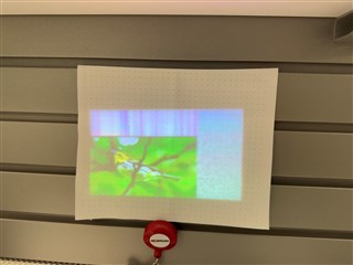
Problems encountered:DLP2021LEQ1EVM development board in the process of testing an abnormal figure (expected to be a color bird picture, but the display is a black and gray dot plot), the laser was suddenly extinguished after a while, and then it could not be lit, and there was no reaction after replacing other images and display frequencies, it was suspected that the laser was damaged, and there was no bump before.

Please help analyze whether the laser is damaged as soon as possible, because we need to replace it

Thanks.

  • Hello,

    I asked a colleague to help with this issue.  However, we do not see any picture or plots.  Did you mean to attached something?  Also the DLP2021LEQ1EVM is based on LED.  Did you mean LED is broken?  


    What do you mean by abnormal figure?

    Jason

  • Also, these EVMs are available and can be reordered here:  https://www.ti.com/tool/DLP2021LEQ1EVM 

  • I will describe the problem in as much detail as possible:
    1. After receiving DLP2021LEQ1EVM evaluation board, the evaluation board is in host silent mode, and the racing video is played after power-on.
    2. After re-powering, enter the fpqa programming mode through the dip switch, change the picture address and download the firmware to make it project color
    Color bird picture, then the picture color and content are normal.
    3, re-switch the dip switch back to fpqa programming mode, about two or three days in this mode no one to use it.
    4. Due to project requirements, we need to obtain RGB timing and light duty cycle, power on the evaluation board, and turn the dip switch back to the host
    The sound mode makes it light, at which time the projected color bird image appears abnormal, first the color becomes black and gray mixed, and then the picture
    The content becomes incomplete, the shape of the bird cannot be seen, and the whole picture shows the dot shape of the residual shadow.
    5, after the picture is abnormal, try to switch the host mute mode and fpqa programming mode back and forth through the dip switch to restore it, but
    It did not work, and the laser suddenly went out after a while, and then switched between the host silent mode and the FPGA programming mode, or heavy
    It's been powered on and off, and it hasn't been lit up again.

    The above is the whole process of the problem. Please help analyze whether the product needs to be replaced as soon as possible, because I have contacted the after-sales engineer of your company, and the after-sales engineer suggested that the product can be replaced only after the judgment of your engineer.

  • The flying line on the evaluation board does not affect the outgoing light signal. Before the laser is extinguished, the timing of the captured outgoing light signal is normal. After the laser is extinguished, the timing of the outgoing light signal is not captured.

  • Hi Zegeng, thanks for the detailed response! I'm beginning to look into this issue this week.

    Would you mind attaching the flash image file you're using on this thread? I would like to keep my setup as similar to yours as possible.

    Thank you,

    Andrew

  • Hi Zegeng,

    I'm sorry for the confusion, but I was referring to the "flash image", i.e., the binary file that you select on the "Flash Programming" page to program to the system. It will be located in the "Outputs" folder of the Composer project directory, and should be named something like "FlashImage.img". Could you please send me that file?

    Thanks!

    Andrew

  • I have asked mengao-zeng to forward the FlashImage.img file to you by email, please check it, if you do not receive it, please try to contact mengao-zeng, thank you!

  • Thank you. I have reached out to MengAo. I'll see if I can track down the cause of this problem once he forwards me the file.

    Regards,

    Andrew

  • Hi Zegeng,

    MengAo says that he didn't receive the file. Would you mind sending it straight to me at a-thomas2@ti.com ?

    Thanks!

    Andrew

  • okay!It has been sent to your email.

  • Hi Zegeng,

    I didn't get an email either. Is it possible that your network is blocking the email? Can you instead attach it here?

    Thanks,

    Andrew

  • Hi Zegeng,

    I just flashed what you sent and see the attached image from my system. Can you ensure that you have HOST_MUTE set correctly and then send a picture of the output from your system?

    Thanks,

    Andrew

  • Yes, the operation of switching from FPGA programming mode to host silent mode to display the picture is completely carried out in accordance with the user manual, and the operation of many times before the laser is not out of the light can be correctly mapped, and there will be no other additional parts like your projection picture, the color bird picture should account for all the projection.
    Are you saying that the addition to the picture means that the image is abnormal, and there is a connection with the laser not emitting light?

  • Hi Zegeng,

    I'm sorry for the confusion. I was actually testing this on a .3" DMD system because that's what I had handy. Because of this, the garbage around the image was expected since the bird picture is not the correct size. On a .2" DMD like you're using the picture correctly fills the screen.

    It does sound like there could be an issue with your LED driver board since you are no longer seeing any light. Can you please verify that both the ribbon cables on the EVM are connected properly?

  • I am quite sure that the two flexible cables are connected correctly, because I have tried to reconnect the two cables several times, but I cannot get the laser to shine properly.

  • Hi Zegeng,

    Thanks for checking that! One other question; has the LED driver or optical engine been modified? These EVMs come with LED modules, not lasers. We'd need to know of any hardware modifications before assisting further.

    Thanks!

    Andrew

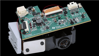
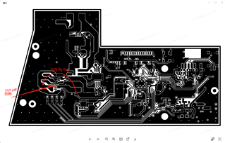
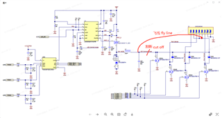
  • Hardware changes are as follows

  • Hi Zegeng,

    Thanks for that information. I've met with the team and we've come up with some debugging steps for you to try:

    1. Remove the optical engine and observe the DMD during operation. If working, you'll see the mirrors flipping to display the selected image/video. Otherwise the DMD could be damaged (potentially from the heat from the laser)
    2. Disconnect the laser from the system and test it with some other stable power supply that fits the spec for the laser. It's possible that the LM3409 is not driving the laser within its spec since this system was designed for LEDs, which generally have a higher tolerance for current swings
    3. Switch back to the original LEDs and see if the system works

    In addition to these debugging steps, we'd like some more information:

    1. What is the part number of the laser? Can you share the datasheet? That will help us determine if the LM3409 is within spec for it
    2. How long did the system work for with the laser installed? Do you have an approximate time that the laser was on for?
    3. What was your goal with the hardware changes? From what you've shared, it seems that you cut the LED Common Anode line only to reconnect to the same trace later; the diodes and FETs are still connected just the same as they were, the current is now just flowing through an external wire instead of the trace
    4. Is this an RGB laser setup or is it monochrome?

    Thanks a lot!

    Andrew

  • Thank you for your debugging suggestion, but we do not know the structure, so it is not good for us to try the debugging steps you suggested. We just hope that we can replace a normal DLP2021LEQ1EVM evaluation board to help us carry out the quick evaluation of the project, because our project cycle is really tight.
    The answers to your questions are as follows:
    1. The part number on the laser is EVM-T02DGPC 2329-0136. I'm not sure what the data table you mentioned refers to.
    2. The FPGA programming mode of the DLP2021LEQ1EVM evaluation board is in the power-on state for about 3 days, the laser is turned on for about 2-5 minutes, and then the laser is extinguished.
    3. We want to obtain RGB power-on timing and current duty cycle data.
    4. RGB laser setup.
    Please help us confirm whether we can replace a new DLP2021LEQ1EVM evaluation board as soon as possible, which is very important to our project, thank you!

  • Hi Zegeng,

    Unfortunately, this EVM is not going to qualify for a free replacement since the hardware has been modified. I would recommend that you order a new system if you need another. In the meantime, I would still like to attempt to debug the cause of this issue to ensure that more damage doesn't occur. Was it another team that modified this system? Evaluating whether or not the laser still works and checking the DMD for damage are important steps to determine exactly what caused the issue.

    Thanks,

    Andrew

  • Hi Zegeng,

    I have some additional questions.

    1. Have you attempted to power the laser in isolation? What if the laser has been damaged? Lasers are generally more sensitive to changes in current than LEDs are.

    2. Please check if the EVM still works with the original LEDs. This is another way to verify if the EVM is the issue or if it is the illumination source. Was the EVM working with LEDs before modification? When you order a new EVM, please perform a basic operational test on the EVM before any modifications. This helps ensure a returnable device in the even that something goes wrong before development takes place. Normally, basic operation is already done at the manufacturer, but this helps ensure a working product. The User's Guide on our TI DLP(R) product pages is generally the first place to look when obtaining our EVMs.
      1. If the EVM comes on fine this way, does it run on the original firmware? Perhaps a change in firmware caused it to malfunction over time?

    3. What voltage source are you using? Is this a regulated power source such as a DC power supply? What voltage is being supplied? What is the current capability? In other words, does the voltage source supply enough power?

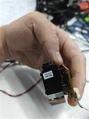
    4. May you send us a picture of the laser? Maybe multiple pictures? I would like to see the part in a picture. I am unable to find this part online: "EVM-T02DGPC 2329-0136." If you have a link for the part, that's even better.
      1. A datasheet for this would be good for us so we can better understand this laser's limitations.

    5. To be certain, the images you have shown depict every change you have done? I am curious in case another team did the work here.

    Regards,
    Michael Ly