This thread has been locked.
If you have a related question, please click the "Ask a related question" button in the top right corner. The newly created question will be automatically linked to this question.
LightCrafter-aficionados,
Young Optics has done a great job in creating a compact light engine for LightCrafter. To explain the light engine, I have disassembled one of our units. I removed the cover on the top and bottom of the light engine. I also removed the Red LED heat sink and the Green and Blue LED heat sink. Note that any disassembly of the light engine voids the warranty on the LightCrafter system.
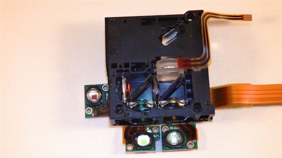
The following photo shows the top side of the light engine. The flex cables supply power to the LEDs. The DLP3000 DMD lies vertically on the top left hand side in front of the projection and focus lenses. The LEDs lie between the heat sink and light engine.
Each LED has an optical collimator to collect the wide beam of light from the LED and produce a narrower beam. This narrow beam of light passes through a set of dichroic mirrors that reflect a specific color of light while letting other colors of light pass through it. The dichroic mirrors recombine the different colors of light into one co-linear beam. The recombined light passes through a fly-eye and condenser lens that provides uniform light intensity. This uniform light intensity beam is directed towards the DLP3000 DMD.
Here are the paths of the red, green, and blue light:
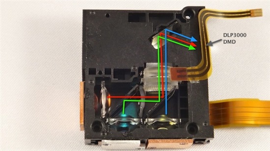
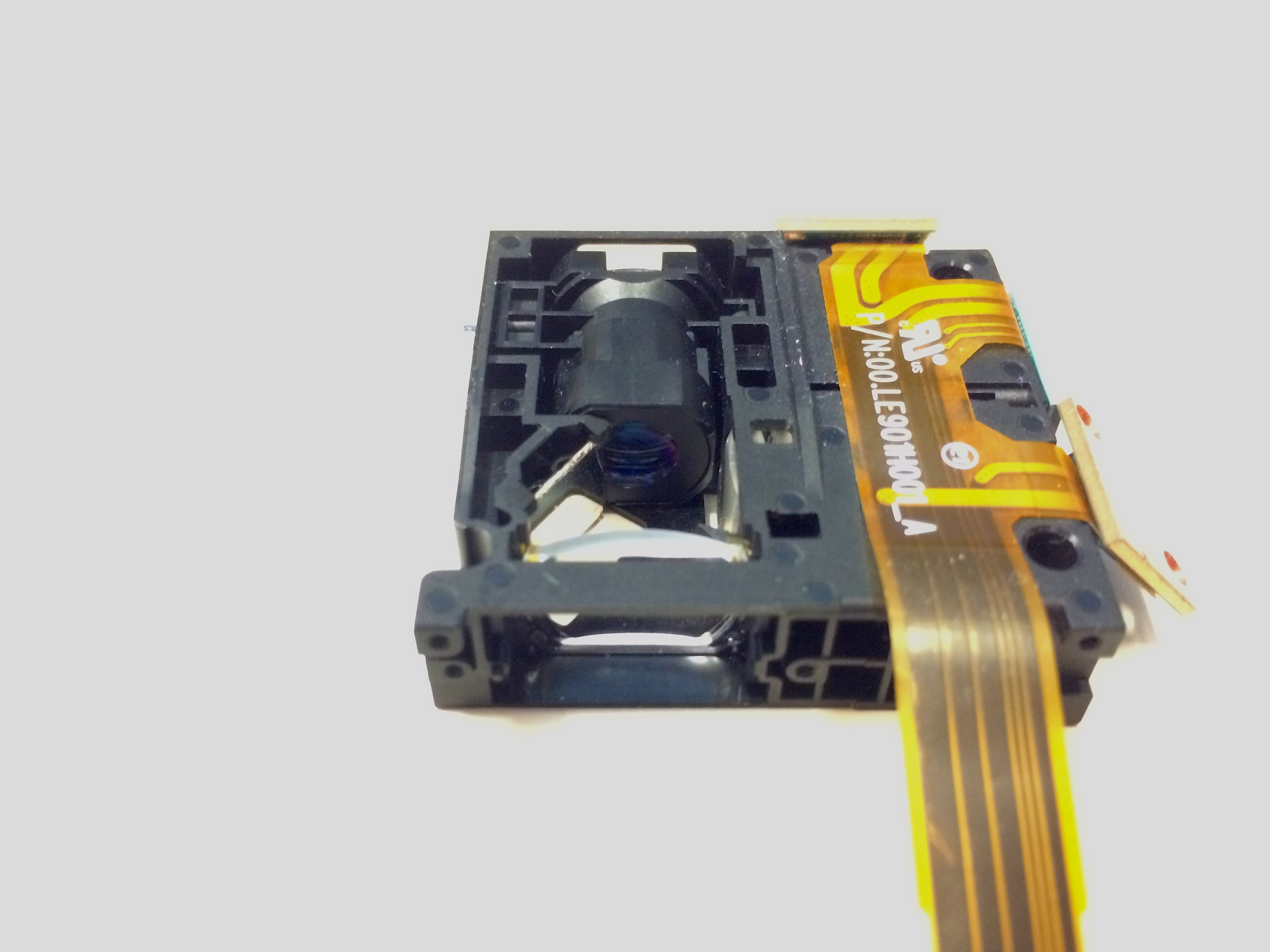
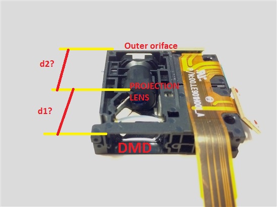
When the DLP3000 pixels are in the on-position, light is reflected through the projection lens. When the DLP3000 pixels are in the off-position light is directed towards a light absorber barrier.
Here is a view of the dichroic mirrors in operation, see how only green and blue light are reflected from ambient light.
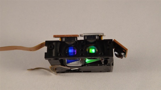
A final photo of the light engine with the LEDs removed. Copper sheets are used to dissipated the heat of the LEDs into the heat sinks. The top and smaller flex cable has a photo sensor next to the condenser and fly-eye lenses. This photo sensor is connected to DLPC300. The Green LED has a thermistor to measure the temperature. This thermistor is connected to a MSP430 ADC channel.
I'm curious about the specific angles involved in the mirror that reflects the light towards the DMD. From the images you've posted, it looks like the mirror sits between the DMD and the output optics blocking light from leaving the projector. Can you provide another image that demonstrates how the light moves around the mirror?
Dear Pedro,
If I wanted to replace one of the R,G,B LED's with a white one, how should I go about this? Are there LED models you would suggests for this operation?
Thanks!
Sam
Hi Sam,
Refer to the LED discussion here http://e2e.ti.com/support/dlp__mems_micro-electro-mechanical_systems/f/850/t/220035.aspx
Regards,
Sanjeev
Hi Sanjeev,
I am curious to know the projection optics when the light is coming from DMD. How many lenses have been used in the projection optics and what are the types of those lenses?
Also it will be better if i can know the distances between DMD and these projection lenses.
Hello Zulfiqar,
We do not have the precise measurement information and lens composition you requested. Young Optics owns that information. Are you needing a reference design for the DLP3000 or are you wanting the specific design used by Young Optics?
Regards,
Eric
Dear TI team,
I am still waiting for the answers regarding my query.
Thanks
Regards
Zulfiqar
Hello Zulfiqar,
Thank you for following up on my question. Unfortunately, we do not have the information you are requesting.
Regards,
Eric
The LightCrafter LED Driver is a modified version of the LED driver shown in section 3 of this application note: Different methods to Drive LEDs Using TPS630xx Buck-Boost Converters
Our modification adds PWM control to the feedback path of the DC-DC converter. A rough circuit is shown by this figure:
This circuit involves controlling several factors to optimize the operation of the LED at a given voltage. Note that in LightCrafter,
With this is mind, the Vadj voltage can be calculated as:
Vadj = Vfb + [(Vpwm * PWM /1024) - Vfb] * R2pwm / (R1pwm + R2pwm)
Current through R3pwm, I3 is given by:
I3 = (Vadj - Vfb) / R2pwm + (Vbias - Vfb ) / Rbias - Vfb / R2 + (Vout - Vfb) / R1
Then the LED current, Iled is given by:
Iled =(Vfb - I3 * R3pwm) / Rilim - I3
With these equations, you can set a max, nom, and min options and explore the range of current though the LED assuming a min PWM value of 1024 and a max PWM value of 1.
Hi PedroGelabert,
I'd like to reduce throw ratio to about 0.6 for wide angle projection.
I know LightCrafter SR1(http://ekb.co.il/pages/products/e4500sr1.php), but this is more expensive than LightCrafter...
Could I do this?
Thanks.