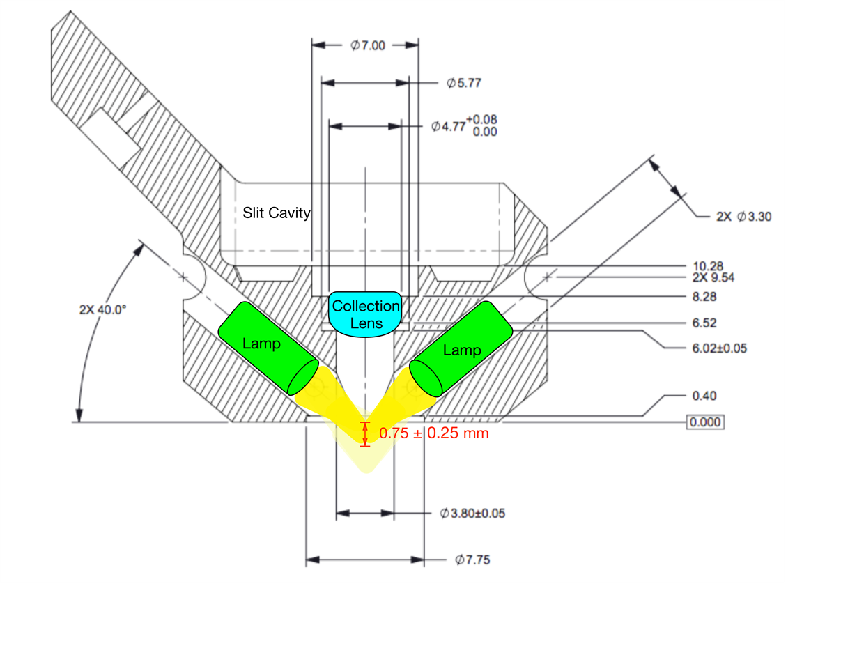
To explain a little more of the optics of the DLP NIRscan Nano Reflectance Illumination module, I have created an illustration to show the converging beams of the two lamps. The following illustration is a top view of the DLP NIRscan Nano Reflectance module. The top of the illustration depicts the cavity for the slit. The bottom depicts the sapphire sample window. The green rectangles represent the lens end lamps. The dark yellow cones are the light outputted by the lamps.
Each lamps produces a beam of light at 40 degree angles that intersect past the sapphire window at about 0.75 mm. There is about ± 0.25 mm tolerance to the beam intersection due to the mechanical tolerances of the chassis, the variations of lens-end from lamp to lamp, the variations of lamp shape, and the placement of the lamps. The lens-end lamps focus the light beam at about 3 mm away and create a spot size that covers the sapphire sample window.
The collection lens gathers light from a 2.5 mm diameter region at the sample window and requires the sample to be placed directly against the sapphire window. If the sample is placed more than 0.50 mm from the window, the sample may not receive enough illumination for the system to perform an accurate scan. Also, the sample must cover the window. If the sample does not cover the window, stray light can enter the system or the sample does not receive and reflect enough illumination for an accurate scan.


