This thread has been locked.

If you have a related question, please click the "Ask a related question" button in the top right corner. The newly created question will be automatically linked to this question.

LED control for shorter wavelength for 3D printing

Other Parts Discussed in Thread: DLP4500, DLPC350

Hi,

I am working with LC 4500 beamer for my DLP 3D printer. I am currently controlling the beamer with LC 4500 GUI software to project required pattern of the sliced images and I have a few queries regarding the settings:

1. I attempted to start 3D printing a few basic models and I saw that the exposure time (8-10 seconds) was not sufficient to cure the resin. I think, I may be wrong, the wavelength of the light was not sufficient enough for the set exposure time. So I wondering if it was because of the pat colour setting chosen by me, as in the pattern sequence (variable exposure time). So my first question is if the pat colour (for eg- red, blue, cyan ,white,etc.) affects the wavelength of the light coming out of the beamer? If it does, what is the recommended pat colour desired for 3d printing applications? 

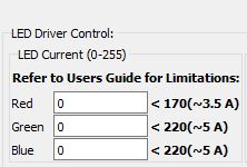
2. Does the LED settings in the top right section affect the wavelength of the light coming from the beamer?. I am talking about the part in the GUI where Red, Blue and Green LEDs have been set at some default current value (104, 130,134 respectively).

I looked up these things in the guide for DLP4500 and DLP 3D printer guide, but I couldn't find anything which would answer my questions. Hence I look forward for some help from this forum. 

Kind Regards,

Anish

  • Anish,

    Referring to your question in #2, the current values do not affect the wavelengths of each LED. Rather, it modulates their brightness/intensity. Since each of the LEDs has its own color, they necessarily have their own light wavelengths. Typically, I believe that a lower wavelength of light (blue being the lowest of RGB) produces the highest image resolution. I'll inquire with my team to help deliver more detailed guidance.

    Best Regards,
    Philippe Dollo
  • Hi Philippe,

    Thank you for your response.

    Just to clarify my question, I was talking about the wavelength of the light being projected from the beamer and not the wavelength of each LED. So I agree that current values don't affect the wavelength of a single LED colour and each LED has it's own wavelength, but does the combination of the three LED currents (as set in the GUI software) affect the wavelength of the light coming from the beamer? or just the intensity?brightness?

    Please let me know after the discussion with your team. Meanwhile I will try to check this too with the projector.

    Really appreciate your help Sir!

    Kind Regards

    Anish

  • Dear Phillipe,

    Do you have any feedback from your team about my questions?

    Kind Regards,

    Anish

  • Hi Anish,

    You may want to consider making hardware modifications in the system. Refer to TI Design on this topic http://www.ti.com/tool/tida-00293 

    Also, make sure you are using wavelength closer to UV range, for example, you can use 420nm LED this is described in the above TI design page in this document http://www.ti.com/lit/ug/dlpu025a/dlpu025a.pdf 

    Regards,

    Sanjeev

  • Hi Sanjeev,

    I have referred to the Tida 00293 documentation and to be honest the base of my question came from the documentation itself. In the figures attached below, do both LED current denote for the same function?


    I could not get the FTDI drivers installed for LC 4500 in my system, hence have been using the GUI interface for sending commands. Is the LED current in the left pic same as the one in the right (DLP 3D printer GUI) ? Because in the GUI the current limitation is 4.3 A whereas in the DLP 3D printer GUI it is set as high as 30.

    Kind Regards

    Anish 

  • My queries has been added in the comment section
  • Hi Ashish,
    Yes, both translate to same command for the DLPC350 controller on the LightCrafter 4500 hardware. Please note that for the 3D printer demo you will be removing the existing the three visible light LEDs and replace 420nm LED at Blue channel place.

    Since it is the same LED driver circuit on the hardware irrespective of the visible or 420nm LED it will be providing the same current level.

    You can do one experiment, if you have o-scope handy, make the same current setting via both the GUI, then look at the current PWM o/p J29 connector on EVM kit, this will show if either settings applying the same current setting.

    J29 connector
    Pin # 8,9,10 for Red, Green and Blue respectively.

    Regards,
    Sanjeev
  • Thank you Sanjeev!

    Regards
    Anish
  • You are welcome Anish.
    Regards,
    Sanjeev