This thread has been locked.

If you have a related question, please click the "Ask a related question" button in the top right corner. The newly created question will be automatically linked to this question.

DLP6500FYE: Query external trigger issue

Part Number: DLP6500FYE

Hello Team,

For my application, I am using an external trigger to cycle through patterns in the DMD(DLPLCR6500EVM). However, the images obviously not show on the mirror.

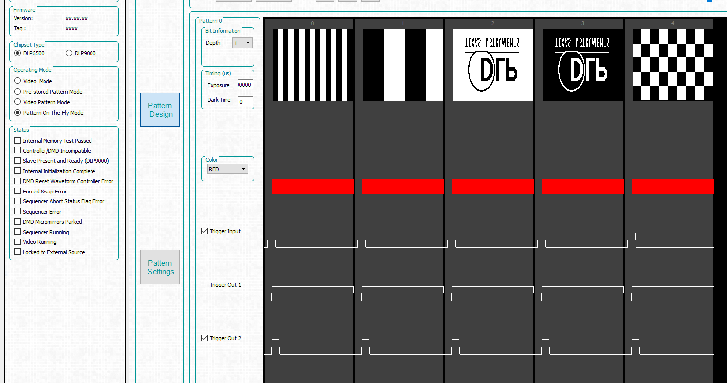
The followings are the setting.

According to user manual, I select pin 23 on j21, j19, and give J20 two signals as shown below.

I use GUI and choose On the fly mode like this.

  The exposure time is 100000; dark time is 0.

I also check the mode without external trigger, and it work normally. Please help me with troubleshooting.

Thanks in advance!

David

  • Hi David,

    Can you check Test Points TP3, TP4 and make sure you see same signal (Voltage Level) you are inputting at J20. This will make sure Voltage level selections are proper.

    Just for testing, can you modify voltage sector jumper to select 3.3v and Input 3.3v Trigger signals instead of 1.8v. Confirm if it works.

    Please Share GUI screenshot with Trigger input option you have enabled and Patterns being used.

    Are you updating LUT after enabling input Trigger ? 

    Thanks,
    Shivakumar.

  • Hi Shivakumar,

    For 1, the test points TP3 and TP4 show the same signal as I give(TP3 == 1.8v 1Hz, TP4 == 1.8v const)

    For 2, The images still not show after changing the selector to pin 12 and give them 3.3v(TP3 == 3.3v 1Hz, TP4 == 3.3v const) signal.

    For 3, this is the GUI screenshot. 

    Yes, I have clicked the Upadte LUT button after turning on the Trigger in.

    David

  • Hi David,

    Thanks for the update.

    Looks like you are using old Firmware and GUI.

    Can you please update the FW to latest version 5.0.1

    Use latest GUI version 4.0.1

  • Hi Shivakumar,

    I update the GUI to 4.0.1 with firmware version 5.0.1. However, the image sequence still not show on the mirror after setting Input Trigger to on state.

    On the other hand, I don't think update the GUI is the solution, since old version GUI can control same hardware theoretically.

    Would the problem be wrong position of other selector?

    David

  • Hi David,

    Thanks for the update.

    I did trigger input testing with the Hardware i have. For me trigger inputs are working fine.

    You could try providing signal at Trigger input 1 as shown below.

    For my testing, i have used FW Version 5.0.1.
    Used attached pattern images and loaded using Pattern on the fly mode.

     6500 DMD OOB Images.zip

    Keeping Trigger input 2 High, when i just provide 3.3v voltage to Trigger input 1, i could see patterns changing on the DMD. 

    Thanks,
    Shivakumar