This thread has been locked.

If you have a related question, please click the "Ask a related question" button in the top right corner. The newly created question will be automatically linked to this question.

JTAG flash programming utility

Other Parts Discussed in Thread: DLPC350, TPS54620, DLP4500

Dear TI E2E Community,

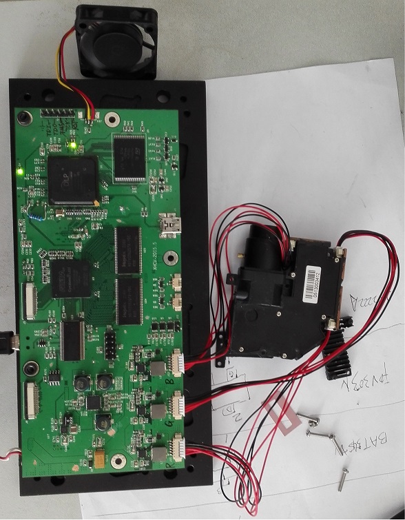
    I am developping my own DLPC350 board. 

    The first thing is programming the empty flash chip. In the forum, "JTAG flash programming utility from TI", where can I find it?   Does it mean "DLPC350 BSDL" in "www.ti.com/product/DLPC350"?


    I have altera usb blaster in hand,  can I program the empty flash with "flash programmer from TopJTAG " and the alter-usb-blaster?

  • We have created JTAG flash tool Appnote, you can create your own referring to the document,  http://www.ti.com/dlp-lightcrafter4500-jtag-flash

    Regards,

    Sanjeev

  • Thanks Sanjeev, 

             I have download the "JTAG Flash Programmer".  With the guide of "DLP LightCrafer 4500 Flash Programming Guide", I connect the UM232H with the  CLPC350 board,  

         But when I do the operation "Board / Detect Chain", an error box appera: "No Device found, Please check the board power, USB/LPT port and JTAG connections".

           The board powered correctly, UM232H, and JTAG connections are all ok,  Where is the problem may be?

  • yes, I made a mistake : the connection of JTAG lines was worng.

    So, now I can erase and program my flash : a single chip M29DW128G. It seems to be.

    the new Sanjeev's FlashDeviceParameters.txt ( I download form e2e community) file seems fit to board with two M29DW128G flash chips, isn't it?

    After the pocess of erasing and programming, the DLPC350 still cannot enum as USB device? Did my programming work fail?
  • How you are programming the flash?

    For easier operation, you can keep the DLPC350 in BOOT_HOLD mode; then program the first 128KB of data. Then reset board, the device should get enumerated, if not your programming is not successful,

    Attach your Flash tool GUI snapshots,

    Did you also attempt verify flash option? Just to make sure the data is written properly? Once the USB is enumerated, you can use LightCrafter 4500 GUI tool to program complete flash image.

    Regards,
    Sanjeev
  • Deer Sanjeev,  

       Thanks for you help. 

      Tried several times, I erased my flash, and program the flash through UM232H with whold bin file. It taks about half an hour.

       After repowered, the HEARTBEAT led is blinking. Is Great!    And the I2C control path is working.  

      Dlpc350 still cannot enum itselp when I connect the USB cable to PC, I didnot know the reason, My board SMT probleming?

      I connect dlpc350 to nothing: DMD_chip, LED-RGB.  And the FAULT_STATUS led is off. Does it normal?

  • Since, hear-beat is there, I think your JTAG program i successful, also you mentioned i2c is working then the problem with USB not working  could be multiple places,

    I suggest debugging in the following oder - 

    1. Use another PC or another USB cable, check if the enumeration works, 

    2. As cross check if you have LightCrafter 4500 EVM handy then make sure the USB and PC are detected with the EVM. Only then go further with debugging your PCB.

    3. Only after you run through 1 & 2, and result is fail, you can proceed to debug your board. As shown below from standard TI reference board - 

    Problem could be with U26 buffer or U27 that will enable USB bus detection J21.

    Regards,
    Sanjeev

  • Thanks for Sanjeev's reply.  Its very important to me.

    I didnot try USB again, There are schemetic or soldering poroblems, perhaps.  My design board have no usb selection circuit, only a resistor connect pin USB_ENZ to GND.

    Whatever, I can program  DLPC350 through JTAG, and control it through I2C, Its enough now to me.

    Thanks!

  • Deer Sanjeev, 

        I think I need your help again. 

      I use FPGA to generate R G B data, P1A_CLK, VSYNC, HSYNC, DATAEN. When power up, The paralel signals are ready. The resolution is 1140*912 * 60 HZ

       And now, when I power up my board:

    1. The fan starts, stop, and then restarts; 

    2. The HEARTBEAT led flashes on and off green. (FAULT_STATUS led is never on during the process.)

    3. My optical engine projects nothing, The R G B - leds are off.

    4. When I read the registers of DLPC350 from I2C, The result here:

    reg 0x20 = 0x1  (Hardware Status is normal)

    reg 0x21 = 0x1  (System Status looks normal too)

    reg 0x22 = 0xA  ( Main Status  )

       I look for "Programmers Guide", It see that reg 0x22 "DMD micromirrors are not parked". 

    Can you give me some advices?  Why I cannot light up my optical engine?   Great Thanks.

  • First try displaying the Internal TPG patterns. If it works then look at this thread where we discuss about reading the video signal detection status e2e.ti.com/.../432488 to narrow down your problem.
    Regards,
    Sanjeev
  • Hi, Sanjeev,    

            The following is my board.   The problem is LED can't light on, still.

             When power up, you can see picture on DMD chip surface, in picture 2, 3.

             Probe by an oscilloscope, LED_PWM signal is about 10KHz,  LED_EN signal is about 240Hz., square wave.

             When i remove the resistances circled in red in picture 4, the LED is on.

            What direction should I consider?     

             1.  top side of my board.

    2. Bottom side.

    3. DLPC4500 chip.

    4. LED_Driver Circuit.  (same with the reference design of LightCrafter4500)

  • Hi,

    Removing R94 and R95 resistors totally take out the LED driver circuit from the DLPC350 control. 

    Is it the same light engine that is offered with the LightCrafter 4500 EVM? If not then probably you have to check with the light engine manufacturer on expected input signals to the LighEngine. 

    Regards,

    Sanjeev

  • Hi,


    Removing R94 and R95 resistors totally take out the LED driver circuit from the DLPC350 control.

    yes,  By this, I make sure, my TPS54620 is ok.

    Is it the same light engine that is offered with the LightCrafter 4500 EVM? If not then probably you have to check with the light engine manufacturer on expected input signals to the LighEngine.


    Light engine is not same with LightCrafter 4500 EVM. But when powerd on, I can see the image on DLP4500 chip, as picture, below.

  • Hi,

    Yes, the DLPC350 to DLP4500 path seems to be good but this will not tell anything related to LEDs not being turned ON.

    From the DLPC350 there will be two signals per each LED, for green channel, it will be GRN_LED_EN & LEG_PWM

    GRN_LED_EN - LED ON/OFF control, when the DLPC350 is operation it will be switching on/off, are you not seeing any toggling here?

    LEDG_PWM - This a PWM setting for current limit setting, the PWM is converted to analog,

    One reason could be the signals be inverted with your driver.

    If you are able to connect the GUI; just set LED control to zero or 255. see if it helps.

    You can also diff b/w connector J32 connector matching to your LightEngine. If it is not electrically compatible it will not work, compatible means, voltage and current ratings, and also connector signals o/p not matching to light engine.

    Regards,
    Sanjeev
  • Hi Sanjeev, 

    If you are able to connect the GUI; just set LED control to zero or 255. see if it helps.

    My board can't able to connect the GUI, but I can read/writhe reigisters of DLPC350 through I2C. The default led current is “97 78 7D”, Whatever I set it to "00 00 00" or "ff ff ff", the LEDs is always off.

    You can also diff b/w connector J32 connector matching to your LightEngine. If it is not electrically compatible it will not work, compatible means, voltage and current ratings, and also connector signals o/p not matching to light engine.

    My RGB leds is very commom, they can be light on with a 3.0V  button battery.

    The follow two image is LED_PWM , and LED_EN signal.

    Thanks.

  • Are you not seeing any changes on GRN_ANODE and GRN_CATHODE point of J32? This is when you are changing the LED_PWM values? The current o/p at this point should start increasing/decreasing at when LED_PWM is changed.

    Regards,
    Sanjeev
  •  NO, there are not any changes on ANODE and CATHODE of LEDs. 


    V(SS/TR) = 3.3V * 1K / ( 9.09K + 1K) = 0.33V  ;   Is not it? 

    and then, How to calculate Vout?  

    (assume LED_EN : 240HZ, 50% duty ratio

         LED_PWM: 10KHZ, 50% duty ratio )

  • This thread discusses the LightCrafter 4500 LED Driver and provides equations for the LED currents. Note Section 3.2.4 of the LightCrafter 4500 EVM User's Guide shows plots of the equivalent LED current and brightness for specific PWM values.

    Please note that the TPS54620 has a ramp up and ramp down delay when it is enabled and disabled. The ramp up and down times are dependent on the design components and layout of the LED driver. For example, this LED driver has a soft start on pin 9. It takes about 99us:

    Requiv = Vref / Iss || R226, where Vref = 0.8V and Iss = 2.3uA

    Tss(ms) = C(nF) * Requiv 

    Your scope plots show that the LED enable is pulsing at 9.98KHz (every 100.1usec) and the PWM is set to 239.4Hz (every 4.18ms). Thus, this rate is too fast for the soft start (99us) combined with the delay through MOSFET (2.7ns).

    One option is to change the soft start capacitor (C279) to 1nF for a 1usec start up delay.

    There is another design based on LM3434 that has faster ramp up and ramp down times. It also provides a wider supply range (9 to 30V). If you look at the LM3434 data sheet, the LM3434 takes in a negative supply, so we shift the system by 12V (12V becomes GND), GND becomes 19V, and provided a 24V input. This app note has the design and the rise and fall times analysis:

  • I am very thankful for PedroGelabert's reply.

    Your scope plots show that the LED enable is pulsing at 9.98KHz (every 100.1usec) and the PWM is set to 239.4Hz (every 4.18ms). Thus, this rate is too fast for the soft start (99us) combined with the delay through MOSFET (2.7ns).


    Frequency of LED_EN IS about 240Hz (decided by V2.0 firmware.)

    Frequency of LED_PWM IS about 10kHz (decided by V2.0 firmware.)

    So,  The enable signal is slower enough (4.18ms) than the softh start time ( 99us ). 

    The voltage on pin 9 is about 0.26v probed by a multimeter on my PCB board, (the chip be locked  with some error?)

    I do the following experiments separatelay.

    A. Remove resistor R227;  (Phenomenon: When powerd up the board,  the leds doesnot light on. )

    B. Remove resistor R227, R224, R226; ( Phenomenon: When powered up the board, the LEDs  ON.)

    C. Remove resistor R227,  replace R226 with a 6.9k resistor , I whish the voltage on pin 9 is about 0.8V; ( Phenomenon: When powered up, the LEDs doesnot light on; the voltage on pin 9 is about 0.2v~0.3v)

    Regards!

  • Thanks, that makes more sense! Sorry the previous message was not clear on what picture was the LED_EN and LED_PWM.

    With regards with your experiments:

    A. Removing R227 will disconnect LED_EN, so the TPS54620 will not power up. This is consistent with your experiment results.

    B. Removing R227, R224, and R226 is more interesting. There is no soft start circuit, as well as, no enable. Is the LED_EN floating high and that is turning on the circuit? The TPS54620 will turn on even if there is no soft start components, as long as enable is high.

    C. The soft start circuit has a current driver and feeds an error amplifier that tries to match the VSENSE (0.8V) threshold. The external resistor divider (R224 and R226) is a way to provide a little more current to speed up the soft start. I believe our production models do not have the soft start components populated.

    Since you are using other LEDs, what are the specs on these LEDs? This circuit was designed for the OSRAM LEDs with a forward voltage of about 2.5V - 3.5V and up to 5A current?

    What is the voltage at PWRGD pin? If this pin is low, there was a thermal shutdown, over-voltage, EN is low, or it is performing the soft start.

    What is your voltage at VSENSE pin?

    What is your voltage at LED Anode when LED_PWM and LED_EN are high?
  • Thanks, 

    A. Removing R227. 

    V(SS/TR)=0.33v;   V(PWRGD)=0V;  V(Vout)=0.25v; V(EN, pin 10)=2.8v; V(VSENSE)=0.76V

    B. Remove R227, R224, R226.

    V(SS/TR)=1.8V;  V(PWRGD)=3.3V;  V(Vout)=2.9v;  V(EN, pin10)=2.8v;

    C. LED_PWM and LED_EN set high (3.3v).

    V(SS/TR)=0.14V;  V(PWRGD)=0V;  V(Vout)=0.25v; V(EN, pin10)=3.3v; V(VSENSE)=0.80v;

    This picture is experiment B.

    Since you are using other LEDs, what are the specs on these LEDs? This circuit was designed for the OSRAM LEDs with a forward voltage of about 2.5V - 3.5V and up to 5A current?

    My LEDs work with a foward voltage of about 2.8v ~ 3.7v,   3.5A(R) or 5A(G & B) max current.

  • PWRGD low of experiment A and C is indicating that the LED driver is not in operational mode.

    In experiment A and C, V(SS/TR) has not reached the threshold of the soft start, so this seems to be the cause of PWRGD low.

    PWRGD high of experiment B is indicating that the LED driver is operating. When LED_EN is floating, the TPS54620 interprets as an enable signal. LED_EN has to be driven low for the TPS54620 to shutdown its output.

    I double checked the schematics on the TI Design with the population options on LightCrafter 4500. R224, R226, and C279 are not populated on LightCrafter 4500. Your experiments verify this condition. Not populating these devices will provide a fast start and drive the output of the LED driver. I will request an update the schematics on the TI design to match the population options of LightCrafter 4500.

    Best regards,
    Pedro
  • Thanks PedroGelaber. 

    Yes, c279 is too large,  it slow down the rise time of SS/TR. 

    Can R224, R226 reallly speed up the charge process?