This thread has been locked.

If you have a related question, please click the "Ask a related question" button in the top right corner. The newly created question will be automatically linked to this question.

OMAP-L138: TIDA-01454 compatibility with TMDSLCDK138/6748

Part Number: OMAP-L138
Other Parts Discussed in Thread: TIDA-01454, , TMDSLCDK138, TMS320C6747, OMAP-L137, PCM1864

Hi,

Is it possible to use PCM1864-Based Circular Microphone Board (CMB) Reference Design (TIDA-01454) with OMAP-L138/6748 Development Kit (LCDK) (TMDSLCDK138/6748)?

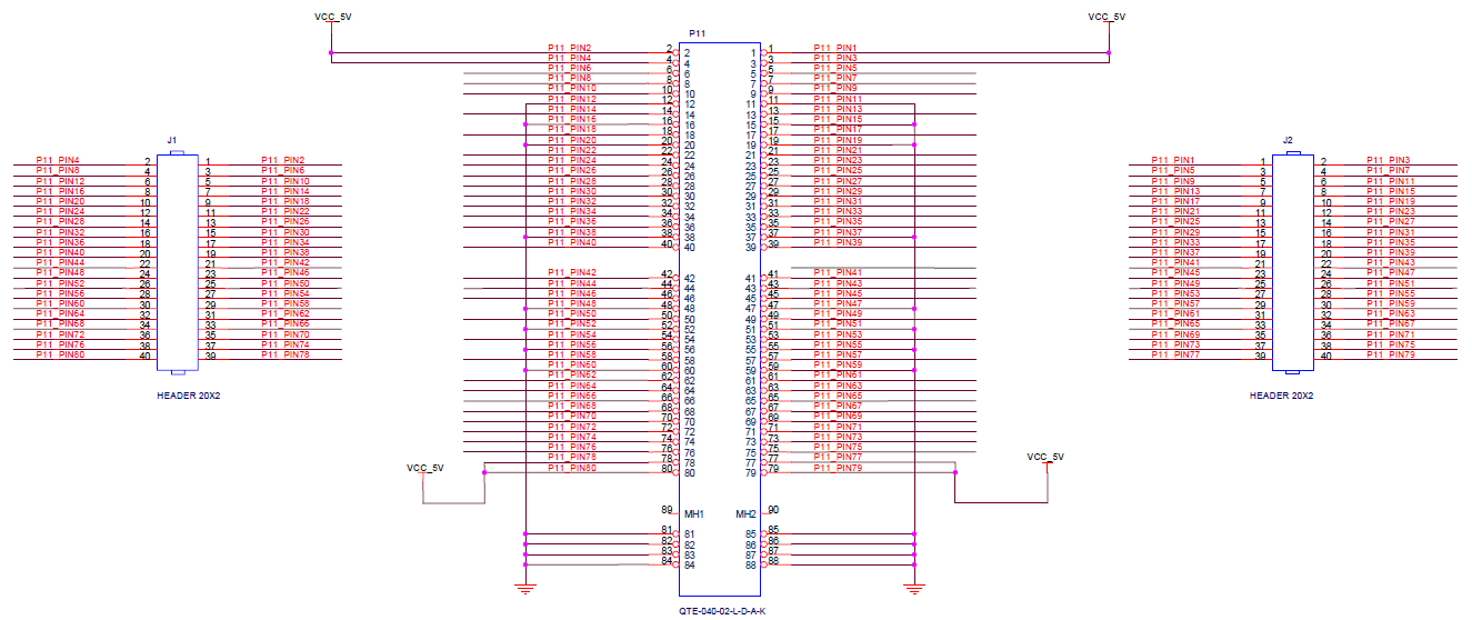
On the TI Designs Forum I got an answer that "Circular Microphone board (CMB) can be used with any host device as it provides access to the I²C control lines and I²S data bus through different connectors. Please refer to the schematic of the CMB to find the available connection points." However, they we not sure if there were free I²C an I²S ports on the TMDXLCDK138/6748 as in the schematics I2C0 is connected to the video codec, and I2C1 is connected to the FTDI chip on both TMDLCDK6748 and on TMDSLCDK138.

Best regards,

Adam

  • The team is notified. They will post their feedback directly here.

    BR
    Tsvetolin Shulev
  • Hi Adam,

    The Circular Mic Board (CMB) can be made to work with the OMAP-L138/C6748 LC Dev Kit, but it will require a blue-wire modification on the LCDK EVM to input all of the microphones. You can get 6 out of 8 without blue-wire modification. See below.

    The CMB definitely works with OMAP-L137/C6747 on the OMAP-L137/TMS320C6747 Floating Point SK.
    See https://e2e.ti.com/support/applications/hirel/f/935/t/678827

    I believe the OMAP-L138 will also work with the CMB, but the EVM is less accommodating (although it is possible).

    The OMAP-L137/TMS320C6747 Floating Point SK uses McASP1 and I2C0_SCL to communicate with the CMB - both are easily available at the P11 header that connects to the OMAP-L137 prototype card.

    The CMB uses I2C, MCLK (optionally), BCLK, LRCLK, and 4 serial data outputs (I2S)

    OMAP-L137 has three McASPs and no McBSPs

    EVM = OMAP-L137/TMS320C6747 Floating Point SK

    - McASP0 has 16 serializers - used by on-board codec (and available at P11 expansion header)

    - McASP1 has 12 serializers - used for CMB at P11 expansion header

    - McASP2 has 4 serializers - used for RMII (and available at P11 expansion header)

    OMAP-L138 has one McASP and one two McBSPs

    EVM = OMAP-L138/C6748 LC Dev Kit

    - McASP has 16 serializers

    - Each McBSP has only one data receive serializer

    - Both McBSPs are pin muxed with the McASP

    - Some MII / Ethernet Media Access Controller (EMAC) are also pin muxed with the McASP

    Below, you can see that all necessary I2C and McASP signals are routed to the J15 header, except only 3 out of the necessary 4 serializers are routed to J15. You will have to solder a wire to a resistor to get the fourth serializer.

    - ACLKX goes to on-board codec and J15 pin 41 !

    - AFSX goes to on-board codec and J15 pin 37 !

    - AHCLKX goes to on-board codec and J15 pin 39 ! (connected to 24.576 MHz U39 OSC through R210)

    - AXR0 goes only to LAN8710A (MII) through R90 series resistor

    - AXR1 goes only to LAN8710A (MII) through R93 series resistor

    - AXR2 goes only to LAN8710A (MII) through R92 series resistor

    - AXR3 goes only to LAN8710A (MII) through R91 series resistor

    - AXR4 goes only to LAN8710A (MII) through R183 series resistor

    - AXR5 goes only to LAN8710A (MII) through R182 series resistor

    - AXR6 goes only to LAN8710A (MII)

    - AXR7 goes to J15 pin 28 !

    - AXR8 goes to J15 pin 32 !

    - AXR9 goes to BOOT SELECT SW1 and R257

    - AXR10 goes to BOOT SELECT SW1 and R258

    - AXR11 goes to BOOT SELECT SW1 and R259

    - AXR12 goes to BOOT SELECT SW1 and R260

    - AXR13 goes to on-board codec and DNI R161

    - AXR14 goes to on-board codec

    - AXR15 goes to J15 pin 36 !

    - I2C0_SCL goes to J15 pin 13 and J16 pin 29 and P2 pin 14 (but P1 is level shifted to 1.8V)

    - I2C0_SDA goes to J15 pin 15 and J16 pin 30 and P1 pin 15 (but P1 is level shifted to 1.8V)

    (I did not check for I2C addresses on the EVM that conflict with the I2C addresses on the CMB)

    If you want to use the on-board codec simultaneously, you will need to ensure that the ACLKX, AFSX, and AHCLKX clocks can operate at the same rate as the PCM186x codecs on the CMB. If you don't need the codec, you could keep it out of the picture by blue-wiring one side of R352 to GND to hold it in reset. It will probably be fine without holding it in reset, also.

    Some links:

    CMB

    http://www.ti.com/lit/df/tidrqt3/tidrqt3.pdf

    OMAP-L138/C6748 LC Dev Kit

    http://www.ti.com/lit/zip/sprcaf3

    OMAP-L137/TMS320C6747 Floating Point SK

    http://support.spectrumdigital.com/boards/evmomapl137/revd/

    http://www.spectrumdigital.com/omap-l137-prototyping-module

    http://www.ti.com/lit/ug/tidud76a/tidud76a.pdf

    - see Table 2. Connections Between CMB and OMAP-L137 Prototyping Board 

    OMAP-L137 PROTYPING BOARD J1, J2, P11 mapping (because I couldn't find it online):

    Hope this helps,
    Mark

  • Hi Mark,

    thank you very much for such an exhaustive and detailed answer! It will take me some time until I try your solution. A few more questions regarding your answer:

    1. I am very familiar with McBSPs but have never worked with McASPs. Are they equivalent with respect to connecting audio codecs? At least at the level of handling the data streams from/to the codec? I have read that McASP is a superset of McBSP in that it allows connecting multiple codecs, while McBSP has only one data I/O line.
    2. I have been working for many years with 6713DSK which uses McBSPs to talk to the onboard AIC23 codec even though the C6713 DSP does have McASPs. Any particular reason for that?
    3. I also understand that I need as many serializers for a given McASP as there are data streams x number of ADCs, in case of CMB: 4 in total, is that so?
    4. The PCM1864 has one DOUT output but the CMB board has to DOUTs per ADC. The other DOUT is on pin 19 of the ADC and it is GPIO3/INTC - what is the purpose of this output? What data is being sent through it?

    Best regards,

    Adam

  • Hi Adam,

    Adam Podhorski said:
    I am very familiar with McBSPs but have never worked with McASPs. Are they equivalent with respect to connecting audio codecs? At least at the level of handling the data streams from/to the codec? I have read that McASP is a superset of McBSP in that it allows connecting multiple codecs, while McBSP has only one data I/O line.

    Thats right. McASP is very similar to McBSP. It works with audio codecs via the same I2S or TDM modes. It supports the same 0-,1-,2- bit delays, 50/50 duty cycle frame sync or 1-bit frame sync pulse, data FIFO and DMA data transfers. It also has some extra features...
    - upto 16 data serializers (inputs or outputs) that use the same BCLK and WCLK
    - a synchronous mode where receiver operates synchronously without needing ACLKR and AFSR (receiver shares ACLKX and AFSX with transmitter)
    - various clock generation options
    McASP cannot emulate SPI, however.

    Adam Podhorski said:
    I have been working for many years with 6713DSK which uses McBSPs to talk to the on-board AIC23 codec even though the C6713 DSP does have McASPs. Any particular reason for that?

    I dont know the reason why they chose to use McBSP over McASP on the 6713DSK. It might have something to do with the pinmuxing. McASP0 is muxed with Timer and both McBSPs, McASP1 is muxed with HPI.
    Choosing the McBSP over McASP would also allow communication with two codecs at different sampling rates, or using one of the McBSPs as a SPI peripheral.

    Adam Podhorski said:
    I also understand that I need as many serializers for a given McASP as there are data streams x number of ADCs, in case of CMB: 4 in total, is that so?

    Yes, when operating each serializer in stereo I2S mode, they can send/receive two channels per serializer.
    They can also operate in TDM mode for 2 to 32 time slots per serializer

    The CMB has 8 microphones and 2 PCM1864 codecs. Each codec inputs 4 microphones and outputs 2 stereo data streams (4 stereo data streams with one BCLK and one WCLK).

    I'm fairly confident that the PCM1864 could have also been configured as a 4-channel TDM stream, utilizing only one DOUT pin per codec (2 data streams each with 4 time slots). McASP can accommodate these streams.

    Adam Podhorski said:
    The PCM1864 has one DOUT output but the CMB board has to DOUTs per ADC. The other DOUT is on pin 19 of the ADC and it is GPIO3/INTC - what is the purpose of this output? What data is being sent through it?

    The PCM1864 can output serial audio streams from both DOUT and DOUT2 pins. Each are configured to output a stereo I2S stream, that is mapped to two of the four microphones connected to each PCM1864.
    Any of the GPIOs can be assigned as DOUT2. These are configurable in the registers (GPIO3 is pg 0 reg 0x11).

    Hope this helps,
    Mark

  • Hi Mark,

    thank you very much again for your very in-depth answer! You have clarified all my doubts.

    Best regards,

    Adam