This thread has been locked.

If you have a related question, please click the "Ask a related question" button in the top right corner. The newly created question will be automatically linked to this question.

TMS320C6748: TMS320C6748: SPI SOMI output has a negtive pulse on the last bit of one byte, which makes data error sometimes.

Part Number: TMS320C6748
Other Parts Discussed in Thread: SYSBIOS, OMAPL138, TMS320C6678

In my system, I use a MCU to communicate with C6748 throught SPI bus. The MCU is SPI Master, and the C6748 is SPI Slave.

The SPI_CLK is 10MHz, POLARITY = 0 and PHASE = 1.

I use C6748 EDMA to drive the SPI SOMI output.

For test, I let the C6748 to output 0xF1F2F3F4F5F6F7

For SPI_CLK= 4MHz, the read data is always right, which is 0xF1F2F3F4F5F6F7.

For SPI_CLK=10MHz, the read data is sometimes right, but sometimes wrong.

The wrong data is:

Read: 0xF1727374757677

Read: 0xF17273F4757677

Read: 0xF1F273F475F677

Read: 0xF1727374F5F677

.......

At first, I thought maybe the POLARITY and PHASE maybe wrong at the two end. But I've checked that they are alright.

And if the POLARITY and PHASE is wrong, the result should be one bit shift.

But you  can see that, the wrong bit always happens to be the 1st bit of a whole byte!

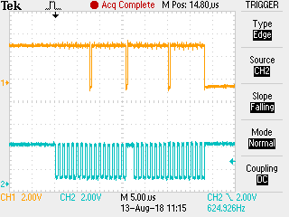
The waveform tells the truth:

This is a waveform between 0xF3 and 0xF4, there is a negtive pulse between the two bytes.

I think this is why my readata is wrong.

Question: Why there is a negtive pulse between the two bytes?

  • Hi,

    Can you post the SPI registers values?

    Best Regards,
    Yordan
  • Hi Yordan,

           Thank you very much for reply.

           Here is the SPI0 registers:

  • These seem correct. What board are you using: a custom board or the LCDK?
    Also which SDK version?
    We can try to reproduce the issue on our side.

    Best Regards,
    Yordan
  • Can you try running the TI RTOS SPI example and see if the problem exist? If not, then you can compare the code against your application and see where your code breaks.

    Best Regards,
    Yordan
  • Thank you very much for reply.
    I used the stareware SPI example. Where is the TI RTOS SPI example? I didn't find the example in the \SYSBIOS\Application directory.
    And, by the way, the negtive pulse between the two bytes is only about 20ns. I don't think it is because of any code break.
    Anyway, I will try the TI RTOS SPI example first.
  • Here is the RTOS download link:
    www.ti.com/.../processor-sdk-c6748

    Best Regards,
    Yordan
  • I mean I had installed the RTOS, but I don't know which example I should take.
    I used the ti\C6748_StarterWare_1_20_04_01\examples\evmC6748\spi example.
    Which example do you suggest? In which directory do you mean is the TI RTOS SPI example?
  • ykovachev@lin-0373:~/ti/pdk_omapl138_1_0_3/packages$ gedit pdkProjectCreate.sh
    ykovachev@lin-0373:~/ti/pdk_omapl138_1_0_3/packages$ ./pdkProjectCreate.sh OMAPL138 all little spi all dsp

    The above commands create folder ~/ti/pdk_omapl138_1_0_3/packages/MyExampleProjects, which contains the spi example project, called
    SPI_LoopbackExample_lcdkOMAPL138_c674xExampleProject

    After you've created the project you can open CCS, import the project, build it and load & execute it on your LCDK.

    Best Regards,
    Yordan
  • Hi Yordan Kovachev,

    Thank you very much.
    I've tried the SPI_LoopbackExample_lcdkOMAPL138_c674xExampleProjec.
    If I comment the line "SPI_control(hwHandle,SPI_V0_CMD_LOOPBACK,(void *) &loop);" which means do not use the interl loop test mode,

    and change the "TEST_SPI_PORT" to "1", I can see the SPI_CLK waveform on the SPI1_CLK pin.
    But if the "TEST_SPI_PORT" is "0", the SPI_CLK waveform is always high on the SPI0_CLK pin.
    Nothing esle changed on the code.
    I've taken a lot time looking through the example code, but havn't find the cause of the problem.

    Why the code does not work for SPI0? Could you please help.

  • And I tried to modify the example to be a Slave example with DMA. But faced some new problems. The documents:
    API_Documentation.html
    ReleaseNotes_SPI_LLD.pdf
    SPI_LLD_SoftwareManifest.html
    are all the documents I have, but I find it difficult to use the APIs correctly.
    Is there any more examples for SPI Slave with DMA?
  • Hi,

    Why the code does not work for SPI0?


    Have a look at the McSPI example guide:
    processors.wiki.ti.com/.../Processor_SDK_RTOS_QSPI-McSPI

    Did you configure the SPI module correctly? See Board Specific Configuration & SoC Specific Configuration.

    Best Regards,
    Yordan
  • Hi Yordan Kovachev,

         Thank you for the example guide.

         Based on the main_spi_loopback_example example, I use SPI0 in Slave mode. Use a 1MHz CLK to connect to the SPI0_CLK.

         uint8_t txBuf[LEN_TXBUF]={0xF0,0xF1,0xF2,0xF3,0xF4,0xF5,0xF6,0xF7,0xF8,0xF9,0xFA,0xFB,0xFC,0xFD,0xFE,0xFF};

         Here is what I got:


    zoom in:     

         The same phenonen happens!!!!

         There is a negtive pulse between the two bytes. In the 1st picture, there should be 3 negtive pulses. But since in the middle of the picture, the code is 0xFA, which is 11111010, so the negtive pulse is sheltered by the last "0" bit, which is shown below. And the width of the negtive pulse is about 80ns in this case (SPI_CLK=1MHz).

          As I thought, that does not matters with the code. The startware code and the RTOS_PDK code have the same phenonmen.

          The 20ns or 80ns negtive pulse is much smaller than the SPI_CLK period, so it has nothing to do with the code. And both the startware and the RTOS_PDK has the same phenonmen. It must be a hardware problem.

          And the phenonmen occurs both in my own designed board and the LCDK development board. And since it occurs between each byte, not in every bit, so it's not a on board hardware problem.

          I think the negtive pulse would be caused by the SPI hardware IP of C6748 chip in SLAVE MODE. 

          I think you can reproduce that phenonmen on your board.

  • We'll need some time to have a look at this.

    Best Regards,
    Yordan
  • Hi Yordan Kovachev,

    Have you reproduce the same phenonmen?

    Best Regards,
    Frank
  • Hi Frank,

    No, I am not an expert on TMS320C6678 RTOS, so I notified the rtos team about this. I tried on linux kernel, but there the spi driver does not support slave mode so I didn't duplicate your problem.

    I will send a reminder.

    Best Regards,
    Yordan
  • Hi Yordan Kovachev,

           I think that does not matters with RTOS. Because I also tried the stareware and modify the program to slave mode, the same phenonmen on SPI0 occored.

           And these days, I also tried the SPI1 with the RTOS SPI example modified to slave mode.

           There is also a negative gap between each byte. While in SPI0, the gap is 300ns.

             Can you give me the email or E2E ID of the TI expert, who is looking at this problem?

              Thank you.

    Frank

  • Hi Yordan Kovachev,

        I'm sorry, does TI still provide technical support for the C6748 DSP?

        I posted this problem since Nov 2017, our team has stuck on this problem for over 3 month. And we've tried many methods on this.

        Till now, we can only use SPI SLAVE at 4MHz. And the product deadline is quite near.

        And we think maybe it's a hardware problem in SPI module in slave mode. You can follow what we've tested in the post.

        Please just let me know whether TI will deal with it or not.

        Thank you.

  • Hi,

    Yes, we do provide support.
    I've escalated this internally. Someone from the hw team should be looking at it.

    Best Regards,
    Yordan
  • Attached  is the CCS project I use. Which is modified to SLAVE mode from the SPI_LoopbackExample_lcdkOMAPL138_c674xExampleProject.

    SPI_LoopbackExample_lcdkOMAPL138_c674xExampleProject.rar

  • Frank,

    Thanks for sharing your CCS project. Can you re-send your modified code? The project includes broken links to the directory where your code resides, but the actual code is not included.

    Regards,
    Melissa
  • Hi Melissa Davenport45,

                Thank you very much for reply.

                Here is the .c file. The file has only a little change from the original example .c file, making it to slave mode.

                Please try to use 1MHz SPI_CLK and then 10MHz SPI_CLK, and watch the waveform.

                There are two problems:

                1) negtive pulse, which I have posted in the forum. The negtive pulse happens both in 1MHz and 10MHz.

                2) in 10MHz, the send out SOMI waveform is totally wrong.

                Thank you.

                B.R.

    Frank

    main_spi_loopback_example.c
    /**
     *  \file   main_spi_loopback_example.c
     *
     *  \brief  Example application main file. This application will read
     *          and write through spi interface by spi loopback enabled.
     *
     */
    
    /*
     * Copyright (C) 2017 Texas Instruments Incorporated - http://www.ti.com/
     *
     * Redistribution and use in source and binary forms, with or without
     * modification, are permitted provided that the following conditions
     * are met:
     *
     * Redistributions of source code must retain the above copyright
     * notice, this list of conditions and the following disclaimer.
     *
     * Redistributions in binary form must reproduce the above copyright
     * notice, this list of conditions and the following disclaimer in the
     * documentation and/or other materials provided with the
     * distribution.
     *
     * Neither the name of Texas Instruments Incorporated nor the names of
     * its contributors may be used to endorse or promote products derived
     * from this software without specific prior written permission.
     *
     * THIS SOFTWARE IS PROVIDED BY THE COPYRIGHT HOLDERS AND CONTRIBUTORS
     * "AS IS" AND ANY EXPRESS OR IMPLIED WARRANTIES, INCLUDING, BUT NOT
     * LIMITED TO, THE IMPLIED WARRANTIES OF MERCHANTABILITY AND FITNESS FOR
     * A PARTICULAR PURPOSE ARE DISCLAIMED. IN NO EVENT SHALL THE COPYRIGHT
     * OWNER OR CONTRIBUTORS BE LIABLE FOR ANY DIRECT, INDIRECT, INCIDENTAL,
     * SPECIAL, EXEMPLARY, OR CONSEQUENTIAL DAMAGES (INCLUDING, BUT NOT
     * LIMITED TO, PROCUREMENT OF SUBSTITUTE GOODS OR SERVICES; LOSS OF USE,
     * DATA, OR PROFITS; OR BUSINESS INTERRUPTION) HOWEVER CAUSED AND ON ANY
     * THEORY OF LIABILITY, WHETHER IN CONTRACT, STRICT LIABILITY, OR TORT
     * (INCLUDING NEGLIGENCE OR OTHERWISE) ARISING IN ANY WAY OUT OF THE USE
     * OF THIS SOFTWARE, EVEN IF ADVISED OF THE POSSIBILITY OF SUCH DAMAGE.
     *
     */
    
    #ifndef BARE_METAL
    /* XDCtools Header files */
    #include <xdc/std.h>
    #include <xdc/cfg/global.h>
    #include <xdc/runtime/System.h>
    #include <stdio.h>
    
    /* BIOS Header files */
    #include <ti/sysbios/BIOS.h>
    #endif
    
    /* SPI Header files */
    #include <ti/drv/spi/SPI.h>
    #if defined(SOC_OMAPL137) || defined(SOC_OMAPL138)
    #include <ti/drv/spi/src/v0/SPI_v0.h>
    #endif
    #include <ti/drv/spi/soc/SPI_soc.h>
    #include <ti/drv/spi/test/src/SPI_log.h>
    #include <ti/drv/spi/test/src/SPI_board.h>
    
    /* Board Header files */
    #include <ti/board/board.h>
    
    #include "regs_6748.h"
    
    #define SPI_INSTANCE 0
    
    /**********************************************************************
     ************************** Macros ************************************
     **********************************************************************/
    
    /**********************************************************************
     ************************** Internal functions ************************
     **********************************************************************/
    
    /**********************************************************************
     ************************** Global Variables **************************
     **********************************************************************/
    #define LEN_TXBUF	16
    
    void GPIOBankPinMuxSet();
    
    /*
     *  ======== Board_initSPI ========
     */
    void Board_initSPI(void)
    {
        Board_initCfg boardCfg;
    #if defined(SOC_OMAPL137) || defined(SOC_OMAPL138)
        SPI_v0_HWAttrs spi_cfg;
    
        /* Get the default SPI init configurations */
        SPI_socGetInitCfg(TEST_SPI_PORT, &spi_cfg);
    
        /* Modify the default SPI configurations if necessary */
    
        /* Set the default SPI init configurations */
        SPI_socSetInitCfg(TEST_SPI_PORT, &spi_cfg);
    #endif
    
    #if defined(evmK2E) || defined(evmC6678)
        boardCfg = BOARD_INIT_MODULE_CLOCK |
            BOARD_INIT_UART_STDIO;
    #else
        boardCfg = BOARD_INIT_PINMUX_CONFIG |
            BOARD_INIT_MODULE_CLOCK |
            BOARD_INIT_UART_STDIO;
    #endif
        Board_init(boardCfg);
        GPIOBankPinMuxSet();
    }
    
    
    /*
     *  ======== test function ========
     */
    #ifdef BARE_METAL
    void main()
    #else
    void spi_test(UArg arg0, UArg arg1)
    #endif
    {
        SPI_Params      spiParams; /* SPI params structure */
        bool            testPassed = true;
        SPI_Handle      hwHandle;  /* SPI handle */
        SPI_Transaction transaction;     /* SPI transaction structure */
        uint32_t        xferEnable,len= 1;
        uint8_t txBuf[LEN_TXBUF]={0xFF,0xF1,0xF2,0xF3,0xF4,0xF5,0xF6,0xF7,0xF8,0xF9,0xFA,0xFB,0xFC,0xFD,0xFE,0xFF};
        uint8_t rxBuf[LEN_TXBUF]={0};
        uint32_t        terminateXfer = 0;
        bool            retVal;
    
    
    #ifdef BARE_METAL
        /* Call board init functions */
        Board_initSPI();
    #endif


        SPI_v0_HWAttrs spi_cfg;
    
        /* Get the default UART init configurations */
        SPI_socGetInitCfg(SPI_INSTANCE, &spi_cfg);
    
        spi_cfg.enableIntr = false;
        spi_cfg.inputClkFreq = 228000000;
        //spi_cfg.pinMode=1;
        spi_cfg.pinMode=0;
        //spi_cfg.csNum=1;
    
        SPI_socSetInitCfg(SPI_INSTANCE, &spi_cfg);
    
        /* Open the Board flash NOR device with the test SPI port
           and use the default SPI configurations */
        SPI_Params_init(&spiParams);
        spiParams.frameFormat  = SPI_POL0_PHA1;
        spiParams.mode=SPI_SLAVE;      		      /*!< Master or Slave mode */
        spiParams.bitRate=10000000;		            /*!< SPI bit rate in Hz */
        spiParams.transferMode=SPI_MODE_BLOCKING;
    
    
        /* Init SPI driver */
        SPI_init();
    
        hwHandle = (SPI_Handle)SPI_open(TEST_SPI_PORT, &spiParams);
    
        //SPI_control(hwHandle,SPI_V0_CMD_LOOPBACK,(void *) &loop);
    
    
        if (!hwHandle)
    
        {
        	testPassed = false;
        	goto err;
    	}
    
        /* Enable transfer */
        xferEnable = 1;
        SPI_control(hwHandle, SPI_V0_CMD_XFER_ACTIVATE, (void *)&xferEnable);
    
    
        /* Write Command */
        //txBuf = 0xA5A5A5A5; /* Test data */
        len = 4;
    
        transaction.txBuf = (uint8_t *) txBuf;
        transaction.rxBuf = (uint8_t *) rxBuf;
        transaction.count = len;
        transaction.arg = (void *)&terminateXfer;
    
        while(1){
        retVal = SPI_transfer(hwHandle, &transaction);
        }
    
        if (retVal == false)
        {
        	testPassed = false;
        	goto err;
        }
    
        //printf("\n Received Data : %x. \n",rxBuf);
    
        if (txBuf != rxBuf)
        	testPassed = false;
    
    	SPI_close(hwHandle);


    err:
        if(true == testPassed)
        {
            //printf("\n All tests have passed. \n");
        }
        else
        {
            //printf("\n Some tests have failed. \n");
        }
    
    }
    
    /*
     *  ======== main ========
     */
    void GPIOBankPinMuxSet()
    {
    	SYSCFG0Regs.PINMUX3.bit.PINMUX3_3_0 = 1;	//SPI0-CLK 	GPIO1[8]
    	SYSCFG0Regs.PINMUX3.bit.PINMUX3_11_8 = 1;	//SPI0-SOMI	GPIO8[6]
    	SYSCFG0Regs.PINMUX3.bit.PINMUX3_15_12 = 1;	//SPI0-SIMO	GPIO8[5]
    	//SYSCFG0Regs.PINMUX4.bit.PINMUX4_3_0 = 1;	//  CS1     GPIO1[7]
    
    	//	SYSCFG0Regs.PINMUX13.bit.PINMUX13_15_12 = 8;//cc2541׼�����	GPIO6[12]
    	SYSCFG0Regs.PINMUX4.bit.PINMUX4_27_24 = 8;	//ESP32׼�����	GPIO1[1]
    }
    
    //void GPIOBankPinMuxSet()
    //{
    //	SYSCFG0Regs.PINMUX5.bit.PINMUX5_11_8 = 1;		//SPI-CLK 	GPIO2[13]
    //	SYSCFG0Regs.PINMUX5.bit.PINMUX5_19_16 = 1;	//SPI-SOMI	GPIO2[11]
    //	SYSCFG0Regs.PINMUX5.bit.PINMUX5_23_20 = 1;	//SPI-SIMO	GPIO2[10]
    //}
    
    #ifndef BARE_METAL
    int main(void)
    {
        /* Call board init functions */
        Board_initSPI();
    
    
        /* Start BIOS */
        BIOS_start();
        return (0);
    }
    #endif


  • Thanks, Frank. I am looking into this and will give you an update mid-next week.

    Regards,
    Melissa
  • Hi Melissa,

    Any update? Thanks.

    Regards,
    Frank
  • Hi Melissa,

    ANY UPDATE? THANK YOU.

    FRANK
  • Hi Frank,

    I’m sorry for the delayed response. I have been looking into this issue but have had some delays in getting a test setup to reproduce.

    One thing I noticed was that the clock signal in your scope shot has a lot of overshoot and noise. This is often caused by a poor ground signal on the scope probe, but it could also indicate a board related issue. Can you send a scope shot with a cleaner clock? You’ll want to make sure that your scope probe is well grounded.

    Regards,
    Melissa
  • Hi melissa

    THE GROUND is well connected. The clk in the diagram is 10Mhz, and my scope is very cheap, so the waveform has big overshot. But that has nothing to do with the negative pulse.

    I think you will see the negative pulse when you setup the test. Looking forward to see your result.

    Frank

  • Hi Melissa,

          These are the waveform I got with 1MHz SPI_CLK. You can see that, since the SPI_CLK is only 1MHz, the overshoot is very small when observe with my scope. And the negtive pulse is still there, about 80ns width.

  • Frank,

    Thanks for sharing these scope shots.  

    Regards,

    Melissa

  • Hi Melissa,

    Any new update?
    Thank you.

    Frank
  • Hi Melissa,

    Any new update?
    Thank you.

    Frank
  • Hi Melissaw,

    What's going on? Are you still looking at this problem?
    Please let me know.
    Thanks.
    Frank
  • Hi Melissaw,

        Since there is no reply from you and TI for 23 days, I wonder whether TI still provide technical support for TMS320C67x DSP? No offence.

        Please just let me know. So that we can move on to other platforms.

        Regards,

    Frank

  • Frank,

    I'm sorry for the delay.  I think I’ve found the root cause of your issue.  It seems to be a configuration mismatch between your SPI Slave and Master.  As shown in Section 28.2.11.3 (Clock Phase and Polarity) of the C6748 TRM, the POLARITY = 0 and PHASE = 1 clocking mode launches on the falling edge and captures on the rising edge.  This matches the waveform you shared, and if the SOMI signal is captured on the rising edge (as specified in the TRM), then the correct value (not the negative pulse) is sampled.  

    Can you confirm that your SPI Master is configured to launch on the falling clock edge and capture on the rising clock edge?   (The Master may not call this configuration POLARITY = 0, PHASE = 1.  You'll want to make sure you check the Master's launching and rising edge.)

    Regards,

    Melissa

  • Hi Melissam,

           No, I think you are wrong.

           In my test, the SPI Slave and Master configuration matches.

           The SPI Master is configured just as launch on the falling clock edge and capture on the rising clock edge.

           What I provide to you is the SPI_CLK and SPI_SOMI waveform. You can see that, the SPI_SOMI is lanched on the falling clock edge. 

           But there is a negtive pulse on the SPI_SOMI, that makes the first bit wrong of every byte!

           If the configuration was wrong, every bit of the data would be wrong, not only happen at the 1st bit!


           Recently, I've made some tests on other configurations. DSP is the slave, MCU is the master.   

           1. DSP and MCU : Polarity=0 or 1, Phase=1   (As described in the post)

               With SPI_CLK=10MHz,  Result:         SOMI has negtive pulse, the first bit of every byte received by the Master would be wrong ('1' will read '0').

               With SPI_CLK=1MHz,   Result:         SOMI does not have negtive pulse. The data read by the Master and the Slave are always right.

           2. DSP and MCU : Polarity=0 or 1, Phase=0

              With SPI_CLK=10MHz,   Result:         SOMI does not have negtive pulse. The data read by the Master and the Slave are always right.

              With SPI_CLK=1MHz,     Result:         SOMI does not have negtive pulse. The data read by the Master and the Slave are always right.

           And what is more, when the DSP is set as Master, the MOSI has the same result (PHASE=1, then MOSI has negtive pulse).

           The conclusion is obvious:

           When PHASE=1, the C6748 SPI peripherial has a hardware bug, which makes the SOMI/MOSI has a negtive pulse. And if the SPI_CLK frequency is high, the negtive pulse will makes the data wrong on the 1st bit of every byte.

           It's very easy to check that. You can see.

           Maybe the C6748 SPI MOSI/SOMI netive pulse will not make the data wrong with some SPI MCUs or SPI Flashes, since the negtive pulse is just after the falling edge (when Phase=1) and the rising edge is far from the negtive pulse when the SPI_CLK has low frequency. But for some SPI MCUs such as ESP32 I used, when the SPI_CLK is 10MHz, the negtive pulse does affect the data capture and makes received data wrong.

           Regards,

    Frank

  • Hi Melissa,


    For my above discription, do you agree? What's your opion and advice?

    Thank you.


    Regards,
    Frank

  • Frank,

    Thanks for sharing your observations for all of these configurations. Your previous waveform with 1MHz SPI_CLK shows the negative glitch. However, your last post says that SOMI does not have a negative pulse for Phase = 1, SPI_CLK = 1MHz. Is that correct? Do you no longer observe this pulse?

    We are currently debugging our test setup so that we can try to reproduce these Polarity/Phase combinations. However, we have a few additional questions:

    1. What oscillator frequency does your board use? 24MHz? 25MHz?
    2. What are your PLL settings?

    Regards,
    Melissa
  • Hi Melissa,

          When PHASE=1, the ouput of the C6748 SPI (MOSI in master mode / MIOS in slave mode) has a negtive pulse at the end of every byte.

          When PHASE=0, no problem.

          1. What oscillator frequency does your board use? 24MHz? 25MHz?

               24MHz.

          2. What are your PLL settings?

               The configuration is attatched below.C6748.gel

        Regards,

    Frank

  • Hi Frank,

    I'm looking for SPI timing diagrams for the ESP32 device you're using but am not finding any. Can you help point me to where I/O timings are published for this device?

    Regards,
    Melissa
  • Hi Melissa,

          I think the attatched document maybe have what you want in PART5.

    TMS320C6748™ Fixed- and Floating-Point DSP (Rev. E).pdf

  • Hi Frank,

    We're still looking into this issue. So far, we have not been able to replicate the low pulse, but I had a question for you--

    Can you set the C6748 to output 0x01020304050607? What do you observe on the scope? Do you see any high pulses between the data bytes, or does everything look normal?

    Regards,
    Melissa
  • Hi melissaw,

             Thank you very much for reply.

             I can replicate the low pulse both in my board and the EVM board, when the first bit of the byte is '1'. For example, when output 0xF1F2F3F4.

            When output 0x01020304050607, since the first bit of every byte is '0', there is no low pulse.

            When in master mode, when the C6748 output 0x01020304050607, yes, the MOSI will be high between every data byte.

            Thank you.

    Frank

  • Hi Frank,

    I believe there's a bug in the SPI driver causing the polarity and phase to not be properly configured in slave mode. 

    To verify this on your end, please try the following experiment:

    Set the frame format to SPI_POL1_PHA1, place a breakpoint after SPI_open(), run to the breakpoint, open the Registers window, and view the SPIFMT register. If you take a look at the POLARITY and PHASE bits, you should see that they are still set to 0. 

    To fix this, add the following code after SPI_open:

    SpiRegs->SPIFMT[0] &= (~(CSL_SPI_SPIFMT_WDELAY_MASK |
                CSL_SPI_SPIFMT_PARPOL_MASK |
                CSL_SPI_SPIFMT_PARENA_MASK |
                CSL_SPI_SPIFMT_WAITENA_MASK |
                CSL_SPI_SPIFMT_SHIFTDIR_MASK |
                CSL_SPI_SPIFMT_DISCSTIMERS_MASK |
                CSL_SPI_SPIFMT_POLARITY_MASK |
                CSL_SPI_SPIFMT_PHASE_MASK |
                CSL_SPI_SPIFMT_PRESCALE_MASK |
                CSL_SPI_SPIFMT_CHARLEN_MASK));
    
    SpiRegs->SPIFMT[0] |= 0x00039508;

    You'll also need to add the following:

    #include <ti/csl/csl_syscfg.h>
    #include <ti/csl/cslr_spi.h>
    #define SpiRegs ((CSL_SpiRegs*)CSL_SPI_0_SLV_REGS) 

    Please try the above experiment and patch and let us know what you find.

  • Hi Sahin Okur,

    Thank you very much for reply.
    I use the stareware SPI_EDMA example. There is no SPI_OPEN(), but there is SPI_Setup().
    I set the frame format to SPI_POL1_PHA1, place a breakpoint after SPI_Setup(), run to the breakpoint, open the Registers window, and view the SPIFMT register. I take a look at the POLARITY and PHASE bits, they are both 1.
    So there is no bug at the SPI_Setup(). But the waveform has negtive pulse as I mentioned in the post.
    As I mentioned, no matter in Master Mode or in Slave Mode, if the PHA=1, there will be negtive pulse between two bytes, if the last bit of the 1st byte and the first bit of 2st byte are both '1'.

    Thank you.

  • Hi Frank,

    What is the frame size on the SPI master? The OMAPL138 SPI expects the frame sizes on the master and slave to match.

    The frame size is configured as 8 bits by default with the PRSDK SPI driver. It is probably the same with Starterware. You can change the frame size with the "spiParams.dataSize" parameter.

    The scope shot below shows the SOMI and CLK waveforms when the master frame size = 16 bits and the slave frame size = 8 bits, sending 0xFFFFFFFF, POL1_PHA1:

    You can see the master transmits a clock every 16 bits, but the slave is expecting it every 8 bits. I think this explains the reason for the incorrect data and negative pulse you have been observing.

    When both the master and slave frame size = 8 bits, the data and wave-forms look good:

    Please try matching the master and slave frame sizes and let us know what you observe.

  • Hi Sahin Okur,

           Thank you very much for reply.

           I am sure the frame size are both set to 8 bits. But the ESP32 (which is the SPI Master) send out all the clocks continously, with no halt on every 8 bit.

         While I have tried the C6748 as master, the C6748 SPI Master will not send out the SPI CLK continously. There will be a halt on every 8bits.

         But I think the SPI standard does not limit the SPI CLK to send out continously.

         I think the cause of the problem may be "C6748 SPI Slave can not accept SPI CLK continously. It does not compile with the SPI standard, it has limitation".

         Maybe you can do the above experiment with another SPI Master which can produce the SPI CLK continously.

         Thank you.

         B.R.

    Frank

  • Hi Frank,

    I have reached out to the design team to get more clarity on this issue. I will post a reply here when I have more information.

    I appreciate your patience.
  • Hi Sahin Okur,

           Thank you so much.

           And the limitation only happens when PHASE=1.

           In fact, for my application, the C6748 and ESP32 can transmit data normally now since I have set the PHASE=0, and there is no negtive pulse. But I think maybe some day other people may also face the problem when they set PHASE=1.

           And the chip I use is TMS320C6748BZCED4. Maybe the problem is related to the special chip.

           Best regards.

    Frank