This thread has been locked.

If you have a related question, please click the "Ask a related question" button in the top right corner. The newly created question will be automatically linked to this question.

DS90UB926QSEVB: DS90UB926QSEVB - lock problem with optical link

Part Number: DS90UB926QSEVB
Other Parts Discussed in Thread: DS90UB929-Q1EVM, , ALP

Hello,

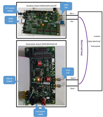
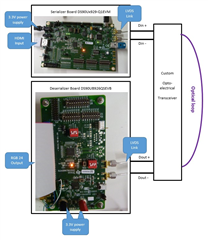
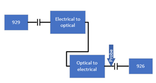
I am planning to use DS90UB929-Q1EVM and DS90UB926QSEVB for converting HDMI to serial and serial to RGB24 data correspondingly,

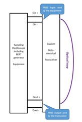
Between serializer and deserializer, we are planning to use unidirectional optical link to transmit the data, so the backchannel communication won't work.

I have lock problem on 926 board even if I deactivate backchannel communication on Serializer by setting bit FORCE_LINK_RDY (register 0x5C, value 0x42 in DS90UB929)

I also deactivate backchannel communication on 926 deserializer (register 0x01, value 0x00).

With electrical link between serializer and deserializer it work. When I replace electrical link with optical link, it doesn't work,

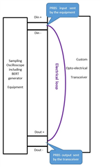
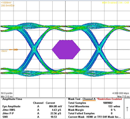
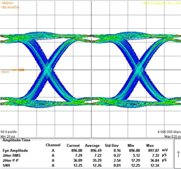
I have checked eye pattern results and I have similar result beween electrical link and optical link.

Do you have any idea of the origin of this lock problem ?

Per advance thank you

Best regards

  • Hi, 

    What do you mean optical link? how are you converting the FPD-Link signal into an optical signal?

    Regards,

    Michael W.

  • Hello Michael,

    Yes, I'm converting FPD-LINK signal into unidirectional optical link. Because of this unidirectional limitation of optical link, I'm trying to use FPD-LINK signal without backchannel communication.

    To inhibit this backchannel communication, I set FORCE_LINK_RDY bit into DS90UB929 serializer device and I reset  BC_ENABLE bit into DS90UB926 deserializer device.

    Unfortunately, I can't lock deserializer device even if serializer device send FPD-LINK signal through the optical link.

    If I replace optical link with electrical link, it works well.

    Is there any other bit to configure into deserializer device to achieve FPD-LINK transmission without backchannel communication ?

    Per advance thank you

    Best regards

    Mickael Chevallot

  • Hi Mickael,

    These devices were not intended to work in this kind of system so there are many things that could be wrong. I suspect this is a signal quality issue at the output of the optical link into the 926. Can you capture an eye diagram of this signal?

    Regards,

    Michael W.

  • Hi Michael,

    I had the same idea concerning quality of signal transmission.

    I have made eye pattern measurements with both kind of link (electrical link and optical link).

    I have similar eye pattern for both links, but it works with electrical link and doesn't work with optical link.

    Here are eye pattern measurement of both link @ 4 GBPS :

     - Optical link eye pattern @ 4 GBPS : (FPD-LINK transmission doesn't work)

    - Electrical link eye pattern @ 4 GBPS : (FPD-LINK transmission works)

    There is a little bit more jitter on optical link, but both eye pattern @ 4 GPBS are similars.

    Is this lock problem due to eye pattern test or due to unidirectional way ?

    Per advance thank you

    Best regards

    Mickael

  • Hi Mickael,

    Your eye diagram looks fine, the 926 lock status does not depend on the back channel signal. Where are you checking the Lock status?

    Another issue could be that the back channel of the 926 is causing noise and reflections on the FPD-link line. you can check this by generating an eye diagram with the 926 connected to the optical adapter and using a high impedance probe to capture the eye diagram.

    Regards,

    Michael W. 

  • You can also try disabling the back channel on the 926.

  • Hi Michael,

    I have aleady tried to disable backchannel on the 926 by resetting BC_ENABLE bit into DS90UB926 deserializer device without any success.

    I'm using DS90UB929 and DS90UB926 evaluation boards to do my tests.

    I'm able to make DS90UB929 evaluation board sending FPD-LINK III signal without backchannel communication.

    - When using electrical link (with the eye pattern perfomance given below) to connect both evaluation boards, the pass led and the lock led are ON on the 926 evaluation board -> It works fine.

    - When using optical link (with the eye pattern perfomance given below) to connect both evaluation boards, the pass led is ON but the lock led is OFF on the 926 evaluation board -> It doesn't work

    That's the reason why I was wondering if backchannel is used for lock operation on 926 device.

    Is there another register (I have only resetting bit BC_ENABLE on register #01) to modify to disable the backchannel on the 926 device ?

    Per advance thank you

    Best regards

    Mickael

  • Hi Mickael,

    That register should disable the back channel. Can you try the 926 connected to the optical adapter and using a high impedance probe to capture the eye diagram?

    It might help for me to know what electrical to optical device you are using, can you send me the part number? 

    Regards,

    Michael W.

  • Hi Michael,

    I can't send part number reference as it's a custom design. But with our device we can work using optical link or using electrical link (by configuring an electrical loopback).

    Here is a block diagram of our test using electrical loopback :

    -> You can notice that PASS and LOCK leds are ON with this configuration : It works well.

    Here is the same block diagram using optical loopback

    -> You can notice that PASS led is ON but LOCK led is OFF with this configuration : It doesn't work.

    For remind, here are eye diagram of both configuration : 

    I hope it can help you to undestand why it doesn't work with optical loop.

    Best regards

    Mickael Chevallot

  • Hi Mickael,

    Thank you for your system setup. All of your eye diagrams have only been with the BERT and not the 926 and 929, correct?

    Can you use the 929, 926 and your optical system to capture an eye diagram?

    Also can you read the HDMI Frequency register when you are doing this test?

    Regards,

    Michael W.

  • Hi Michael,

    That's correct, I made eye pattern measurements without the 929 and 926 evaluation boards.

    Can you explain how I can do eye pattern with 929 and 926 devices as, on the 929 side, the input is HDMI port and, on the 926 side, the output is RGB24 port ?

    Do you have a block diagram on the system setup to do this measurement ?

    Per advance thank you

    Best regards

    Mickael Chevallot

  • Hi Mickael,

    you can use the 926's CMLOUT to generate an eye diagram, or you could use high impedance probes on the AC caps by the 926. 

    Regards,

    Michael W.

  • Hi Michael,

    OK to connect CML_OUT signal of the 926 to the eye pattern equipment.

    But can you precise where, on the 929, I should connect the PRBS signal sent by the BERT equipment ?

    Per advance thank you

    Best regards

  • Hi,

    "But can you precise where, on the 929, I should connect the PRBS signal sent by the BERT equipment ?" 

    I am not sure what you mean here. you should not test the 926 and 929 with an external BERT signal.

    Regards,

    Michael W.

  • Hi Michael,

    I'm sorry but I'm not used to working with this kind of products (serializer and deserializer devices).

    Do you mean that I should configure serializer device by using internal pattern generator, as described in the 929 datasheet ?

    If yes, which pattern should I select to test our optical device ?

    For sure, I can use the ALP software interface to monitore the pattern generation.

    Per advance thank you.

    Best regards

    Mickael Chevallot

  • Hi Mickael,

    you can use the 929's pattern generator to send our a test pattern. To do this you should change the Timing source to "Internal" then check "Color Bars" and "Enable Generator".

    Regards,

    Michael W.

  • Hi Michael,

    OK thank you for the information. I will try to do this eye pattern measurement beginning of next week and I will keep you informed.

    Best regards

    Mickael Chevallot

  • Hi Michael,

    I have tried to do eye pattern measurement but our eye pattern dipslay equipment need a synchronized clock input signal.

    I didn't find on the 929 serializer datasheet and on the 926 deserializer datasheet, the pin dedicated to generate any synchronized clock signal to monitore eye pattern display equipment.

    How can I send a synchronized input clock signal to our eye pattern display equipment  ?

    For information, I've tried with only 929 and 926 directly connected together.

    I've configured 929 following your recommandation  (internal source, color bars and enable generator).

    I've configured 926 by enabling CML outputs (register 0x56, value 0x00).

    I've also tried to use PCLK signal as synchronized clock but it didn't work (I wasn't confident by using PCLK signal for synchronization, but it's just for information).

    Best regards

    Mickael Chevallot

  • Hello Mickael,

    There is no way to generate a synchronized clock signal here, so our suggestion would be to use scope equipment for this analysis which allows for taking an eye diagram measurement using only the signal under test which is a common feature for high speed scope equipment that would typically be used for this type of system analysis 

    Best Regards,

    Casey  

  • Hello Casey,

    Unfortunately, I don't have high speed scope to do this measurement.

    I only have TDR equipment for eye pattern measurement.

    Apart from this test, is there another possibility to analyze why lock is working with electrical link and not working with optical link ?

    Maybe it exists some information stored in internal register of 929 and/or 926 devices that could help to identify the problem. Do you have any information concerning internal registers information that could help to understand the origin of the problem ?

    For remind, I have configured both 929 and 926 devices without backchannel communication by setting FORCE_LINK_RDY bit into DS90UB929 serializer device and resetting  BC_ENABLE bit into DS90UB926 deserializer device.

    Per advance thank you

    Best regards

    Mickael Chevallot

  • Hello Mickael,

    It is difficult for us to provide any further steps for you on this issue without being able to see what signal is actually making its way to the DES in this topology. Because the optical transceiver is essentially a black box to us - we do not know anything about what it is doing to the signal between SER/DES and FPD-Link is characterized as a closed system from the TI side, meaning that we do all our validation of the link without active devices in-between. I can tell you that other companies have been successful in implementing the topology that you are trying to achieve here, but the details of the optical module configuration are not known to us on the TI side since we only own the FPD-Link device portion. I would highly suggest to acquire the proper equipment to evaluate the high speed signal after the optical module in order to debug this further 

    Best Regards,

    Casey 

  • Hello Casey,

    Thanks for your answer. If other companies were successufully used 929 and 926 devices with wireless or optical link, it's comforting.

    To be honest, I was worried that a physical electrical contact was required.

    Can you confirm that lock failure is only due to signal quality and not requiring electrical and/or physical link ?

    If yes, I will try to optimize equalizer and de-emphasis configuration.

    Best regards

    Mickael Chevallot

  • Hi Mickael,

    Physical electrical contact is not required, you can tell by the AC caps on the FPD-Link lines. I can only confirm that the lock status will show locked when the 926's PLL is able to lock onto the FPD-Link signal and properly decode the FPD-Link. If the 926 gets a signal that is the proper pattern, frequency, signal height, jitter, skew between + and -, low noise, then the 926 will lock onto the signal. You can try that, but it would probably be easier to view the signal from a high speed oscilloscope. 

    Regards,

    Michael W.