Part Number: DS125DF111
Hi TI technical support team,I have encountered the following problems and hope to get your help,TKS!
I have a SFP+ module project which use DS125DF111 .I use the B channel, and I am going to work at 1.25Gbps and 10.3125Gbps,but I can’t lock it in now.The following is my register configuration table
ADDRESS WRITE VALUE WRITE MASK
0xff 0x0d 0x0f
0x00 0x04 0x04
0x0a 0x0c 0x0c
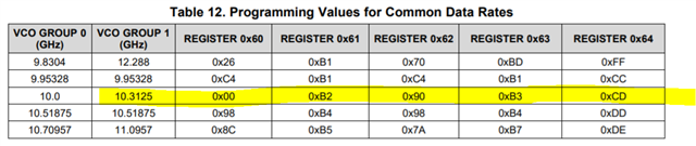
0x60 0x00 0xff
0x61 0xb2 0xff
0x62 0x90 0xff
0x63 0xb3 0xff
0x64 0xcd 0xff
0x31 0x00 0x60
0x2d 0x08 0x08
0x03 0x00 0xff
0x3a 0x00 0xff
0x1e 0x08 0x08
0x2d 0x00 0x07
0x15 0x44 0x47
0x0c 0x00 0x08
0x0a 0x00 0x0c
my question is:
1. Is the lock signal related to bit3 and bit4 of register 0x02? If the signal is locked, 0x02[3&4]=1. Is my understanding correct?
2. Is the signal detected related to bit7 of register 0x54? If a signal is detected, 0x54[7]=1, right? In addition, no matter what signal it is, as long as the signal strength reaches the threshold, it can be detected, right?
3. How to use Enable Interrupt(0x56) and Interrupt Registers(0x01&0x54) correctly?I want to know status of CDR lock/CDR loss of lock/Signal Detect/Loss of Signal,How should I detect in the main program?
4.Is my above configuration correct, why can’t it be locked?
Regards,
kevin