This thread has been locked.

If you have a related question, please click the "Ask a related question" button in the top right corner. The newly created question will be automatically linked to this question.

DS110DF410: Repeater cannot be locked at 4.8G

Part Number: DS110DF410

Dear Expert 

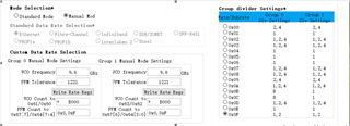
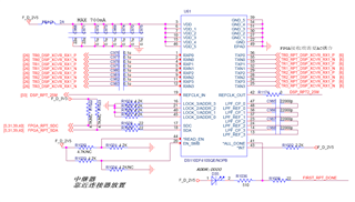
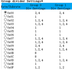
Set it up as shown in the figure below.The rate of input data stream is 4.8Gbps and the signal quality is good.But the repeater cannot be locked at 4.8G.With oscilloscope observation, it can be locked at 4.8G.Would you like to ask what may be the cause?

  • Your settings look correct.

    1. Can you please confirm the exact data rate and test pattern that you are using?
    2. What value are you observing for channel register 0x02 for the retimer channel in question?

    Thanks,

    Rodrigo

  • Hi Rodrigo

    1. The actual data rate is 4.8Gbps, and the test mode is PRBS31.

    2. The output data mode is RAW DATA,CDR has been bypassed.

    One question I want to confirm is that if set to RAW DATA mode, will the repeater introduce additional bit error rate during data transfer?Because we have detected a bit error rate of 10E-6 on the receiving end, normally the bit error rate should be 0.

  • You should not need to bypass the CDR. The TI retimer should have reasonable performance at 4.8G rate with CDR bypass. However, please note that the Rx EQ is not auto adapted when CDR bypass mode is enabled. Instead the user needs to manually set the CTLE for this  case via channel register 0x03. Refer to the datasheet register map for details.

    Thanks,

    Rodrigo Natal

  • Dear Rodrigo

    Thanks for your replying.

    Could you help me review this schematic ,many thank!

  • See my inputs below. I did not find any issue, other than I don't see AC coupling caps on Tx outputs. See note below.

    Checked and ok

    • VDD decoupling
    • REF_CLK_IN -> 25MHz oscillator reference
    • ADDR pin strap options
    • SCL and SDA
    • High speed inputs and outputs
      • External AC coupling caps implemented on retimer inputs
      • Note: I don’t see AC coupling caps on the retimer outputs. Perhaps the FPGA has integrated AC coupling. External AC coupling is required for retimer Tx outputs as well
    • External LPF components
    • EN_SMB -> 4.7kOhm pullup to VDD for normal operation in SMBus Slave mode
    • READ_EN_N -> pulled low for normal operation in SMBus Slave Mode
    • ALL_DONE_N
    • INT_N

    Thanks,

    Rodrigo Natal

  • Dear Rodrigo

    Thanks!

    The output AC coupling capacitor of the DS110DF410 is placed at the receiver of the FPGA.The output AC coupling capacitance is about 15 inches from the output pin of DS110DF410.Would like to ask the output AC coupling capacitor is placed too far, will it affect the signal quality?

  • Thanks. This AC coupling capacitor placement is ok.

    -Rodrigo

  • Hi Rodrigo

    1.As shown in the figure below, assuming input data rate is 4.8Gbps, VCO is 9.6Gbps, CDR mode, then which rate/subrate should be chosen in the figure below?And what's the difference between 0x02 and 0x03, not both 1,2,4?

    2. If only one channel is used, should the other three channels be closed?If not, will there be other effects?

    3.If there is no problem with the input data of the repeater (the eye map is of good quality, stable at a certain rate) and the register setting is also OK (I have checked with you before), are there any other factors that cause the failure of locking?

  • Dear Rodrigo

    Thanks for your replying!

    1.As shown in the figure below, assuming input data rate is 4.8Gbps, VCO is 9.6Gbps, CDR mode, then which rate/subrate should be chosen in the figure below?And what's the difference between 0x02 and 0x03, not both 1,2,4?

    2. If only one channel is used, should the other three channels be closed?If not, will there be other effects?

    3.If there is no problem with the input data of the repeater (the eye map is of good quality, stable at a certain rate) and the register setting is also OK (I have checked with you before), are there any other factors that cause the failure of locking?

    BR

    Garbiel

  • See my inputs below.

    1. "1,2,4" divider ratios option should work for your case. These two options are the same
    2. You may chose to power down unused channels. 

      3.24   Disable Unused Channels

      Disable and power down unused channels. This is recommended for all channels which are not used in an application in order to achieve the minimum power consumption.


      Table 37. Disable and Power Down Unused Channels


      STEP


      SHARED/CHANNEL REGISTER SET


      OPERATION

      REGISTER ADDRESS [HEX]

      REGISTER VALUE [HEX]

      WRITE MASK [HEX]


      COMMENT


      1


      Channel


      Write


      14


      40


      40

      Force signal detect status to 0 (that is no signal detected).

    3. Please provide a fulll retimer channel registers dump for the problem case in question. In particular I'd like to see the value of channel registers 0x02, 0x03, 0x2D, 0x31, 0x2F, and 0x60 thru 0x64  

    Thanks,

    Rodrigo