This thread has been locked.

If you have a related question, please click the "Ask a related question" button in the top right corner. The newly created question will be automatically linked to this question.

TPS65987D: + TPS55288 configuration

Part Number: TPS65987D
Other Parts Discussed in Thread: TPS55288, PMP40801, , TIDA-050012, TPS65987

Dear TI support team

Bellow is the very simplified diagram of my custom design:

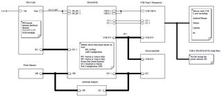
I used the "Docking USB Type-C power delivery refrence design (PMP40801)" and "USB Type C Power Delivery Source with TPS65987D and TPS55288 application report (slvaeq7)" and is working.

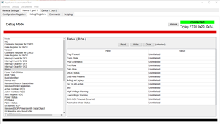
As you can see in the image above, I configured the TPS65987D (using Application Configuration Tool version 6.1.2 via Aardvark Adaptor) to advertize 5V/3A, 9V/3A, 15V/3A and 20V/3A capabilities. Both Power Ports 1 and 2 are set to source only and power due mode has enabled. Also the port configuration is set to DFP and I2C3 has configured as master and sends command to TPS55288 after negotiation.

Here's my questions:

Q1: How to configure the TPS65987D  as UFP whilst both PP Switches are set to 'Source Only' and 'Power Due Mode' has been selected? (My attempts weren't successful) (If I erase the flash memory and disconnect the power supply (14.5V one), I can communication to my firmware on Microcontroller via PC using a USB A to USB C cable. In other word, the microcontoller's USB (2.0) on my board will be enumerated by Windows 10)

Q2: When I connect my board to TI's 'USB-C-PD-DUO-EVM'; sink part, via a power rated USB C cable, whilst the input power for TPS55288  is 14.5V, both boards negotiate and D201 LED on sink board turns on. If I push the S201 button the negotiation is successful and D202 LED lits up for 9V power delivery and I can measure ~9v at PP_HV pins on my board. Now, if I push S202 to go up to 15V, the TPS65987D will damage. I lost two prototype boards because of that. If I power up the damaged boards the TPS65987D get hot very very fast and can not communicatte with PC. I wonder why? I'd like an extra eye balls on this matter.

I exactly send the following commands from TPS65987D to TPS55288 according to slvaeq7.pdf document:

(Power On Reset event) Setting VRef to 0.282 mV for 5 V output, Data 0xd200 with a length of 3
(Power On Reset event) Selecting the divider 0.0564, Data 0x0304, Length 2
(Power On Reset event) Enabling the output, Data 0xa006, Length 2

(Source PDO 1 Negotiated event) (Set to 5 V): Data 0xd200, Length 3
(Source PDO 2 Negotiated event) (9 V): Data 0x19a00, Length 3
(Source PDO 3 Negotiated event) (15 V): Data 0x2c500, Length 3
(Source PDO 4 Negotiated event) (20 V): Data 0x3bf00, Length 3

(Detach event) (Set back to 5 V): Data 0xd200, Length 3

Regards,

Majid

  • Q1:  The easiest way to to this is to create a new project targeted at the TIDA-050012 Source Board.  This is the power duo source board and it will configure the switches to meet your requirements.

    You do need to configure the device as a UFP (Device) for USB 2.0 communications.  

    1.  Enable USB Communication Compatible in the Autonegotiate Sink register

    2.  Configure Transmit Idenfity Data Object to match you MCU configuration as a PDUSB Peripheral and set the Data Capable as USB Device to high

    You will then need to change the GPIO configurations and add you I2C configuration into the project.

    Q2.  This will be easiest to debug if you can attach you project file to this thread so that I can review it.  In order to damage the TPS65987D this way, it usually involves a configuration issue.

    Regards,

    Chuck

  • Dear Chuck

    Thanks for the answer you've provided and sorry about the delay as I have to attend other projects.

    I did what you explained with no chance of working (working means USB enumeration whilst charging on Android devices)

    With the configuration according to your suggestion:

    Scenario 1: Connecting my board to PC (USB A to USB C cable), no charging will happen, USB enumeration will happen by Windows, all Ok as expected.

    Scenario 2: Connecting my board to Android phone directly (USB C to USB C cable), fast charging will happen but USB won't enumerated hence there won't be any communication. This is the scenario that I want it to work.

    Now connecting the Android phone (Samsung Galaxy S8+ with Android 9) to a USB-C hub like "Sitecom CN-386" (Sitecom — CN-386 — USB-C Hub 4 Port) which has one charging USB-C port (100W power delivery) and three NONE charging USB-C ports (7.5W slow power charging).

    Scenario 3: Connecting my board to CN-386 charging port (100W) (USB C to USB C cable), fast charging will happen but USB won't enumerated so no communication.

    Scenario 4: Connecting my board to any CN-386 none charging ports (7.5W) (USB C to USB C cable), no charging, but communication will work.

    For some reason the configuration is not working.

    I attached the configuration project to this ticket for you to have a look. These are some notes:

    Note 1: I removed all three virtual devices (1 ~ 3) as I don't have push buttons to manually advertise the capabilities, nor I have any GPIO outputs. So all GPIOs in 'I/O Config' page are disabled except I2C3 GPIO#5 and GPIO#6 used to control TPS55288 chip.

    Note 2: My I2C_ADDR address in 'General Setting' tab is 0x23.

    Note 3: For now, I only advertise 5V power delivery in 'Transmit source capabilities' page.

    Note 4: No sink capabilities.

    Note 5: In the page 'Transmit Identity Data Object', I don't have 'Certificate Test ID' and 'BCD Device' so I set them to 0x0. But the vendor ID and Product ID are as same as ones in my onboard micro-controller. I unchecked the USB Host data capable checkbox.

    In regards to my second question, you mentioned that a configuration issue can cause the chip to be damaged. I wonder what those wrong settings would be?

    Regards,

    Majid

    Source_5V_Only.pjt

  • Dear Chuck

    I put the Application Customization Tool in debug mode (which is connected to my board) and grabbed some screenshot from the Status Register.

    1. No cable is connected to my board:

    2. The USB-C cable is connected to my board but the other end is not connected:

    3. The USB-C cable is connected to my board as well as Android mobile phone:

    Regards,

    Majid

  • Majid,

    You may need to utilize a USB2.0 protocol analyzer to determine what is happening with the USB interface.  As long as you have the TPS65987 configured to advertise that USB 2.0 data is present, then there is not any other interaction that is required.

    The fact that a windows machine is able to enumerate the BUS show that you hardware is functional, so the issue is likely a protocol mismatch.

    Can you check the Status register when connected to you phone?

    This should tell you what the Data Role for the part is.

    Do you have a PD analyzer?  We use the TotalPhase PD Analyzer extensively:  Here is a link to their web page: https://www.totalphase.com/products/usb-power-delivery-analyzer/  This will let you provide me with the PD traffic and significantly improve how much I can help with your debug.

    Regards,

    Chuck

  • Dear Chuck

    Thanks for the response.

    The third image in my previous post shows the Status register of my board, whilst connected to the phone.

    It says the Data Role is: 'PD Controller is DFP'

    (Please look closer to Status Register fields 'Plug Present' and 'Conn State' in all three images. In second image, as soon as I connect the USB-C cable; whilst the other end of cable is NOT connected to any device, the TPS65987D detects Ra which means power cable is attached.)

    (Please note that the Port Configuration has been set to DFP in the register 0x28, I think this is correct for source only power due mode. I think after PD source negotiated, the data roll should switch to UFP from DFP. Are my settings in Port Control (register 0x29) page correct)

    Did you check my configuration project?

    Finally, I don't have a PD Analyser.

    Regards,

    Majid

  • Majid,

    I checked your status capture and it is reporting that the device is a UFP which is correct for a device, so see any issue that is caused by the TPS65987 in your system, so any issue is likely to be on the MCU to enumerating.

    I did notice that in your DP alternate mode, so are advertising that you support both UFP and DFP which is unusual, so I suggest that you check to make sure that your configuration matches your intention.

    Regards,

    Chuck

  • Dear Chuck

    Thanks for your response.

    I fixed the problem by enabling 'Initiate Swap to UFP' and disabling 'Process Swap to DFP'.

    You mentioned that I am advertising both UFP and DFP in DP alternate mode, which page are you talking about?

    Regards,

    Majid