This thread has been locked.

If you have a related question, please click the "Ask a related question" button in the top right corner. The newly created question will be automatically linked to this question.

DS90UB953-Q1EVM: Performing CTP tests on the EVM

Part Number: DS90UB953-Q1EVM
Other Parts Discussed in Thread: ALP

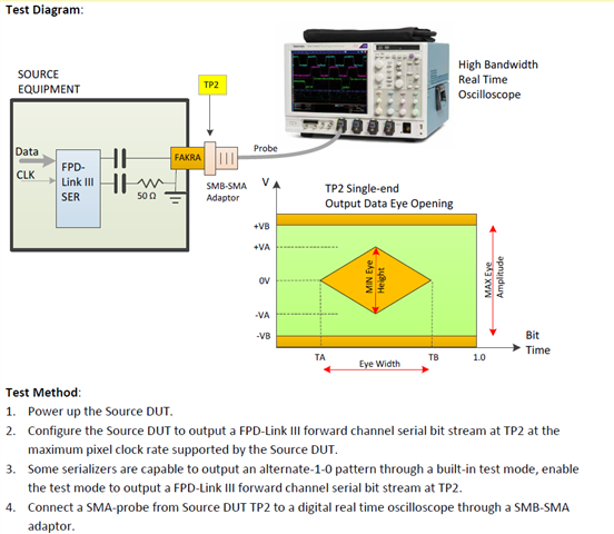
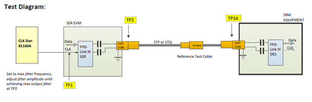
I am looking to perform the specific steps mentioned in the referenced image. Can you please comment if the DS90UB953 can be configured for this? 

Once connected to the scope, how can I control the line rate of the DS90UB953 ? I would like to analyze at the maximum speed of 4.16Gbps.

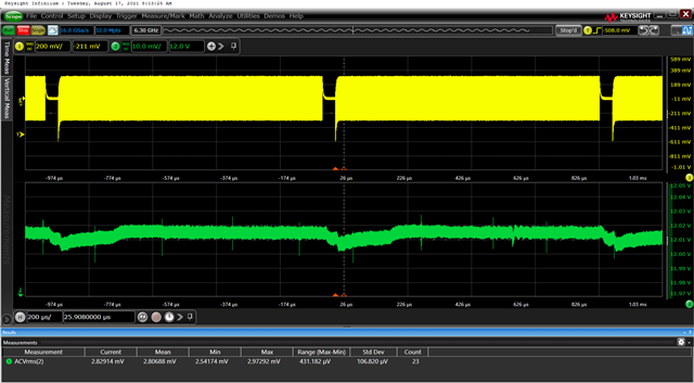
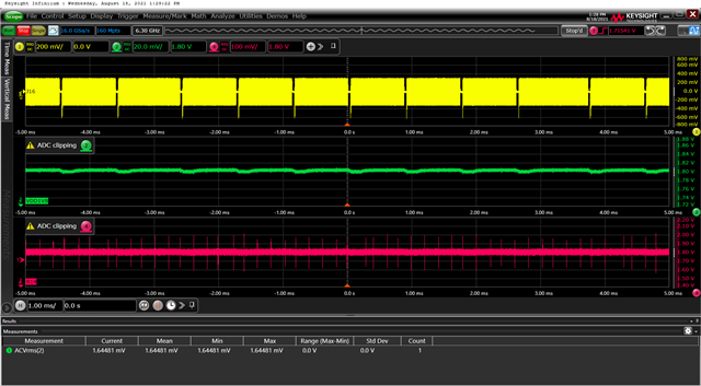
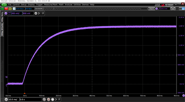
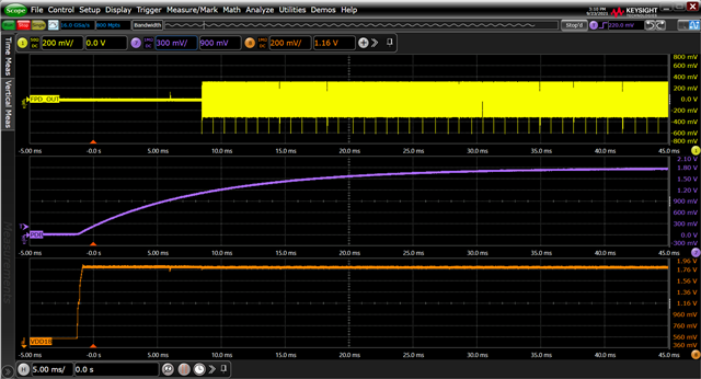
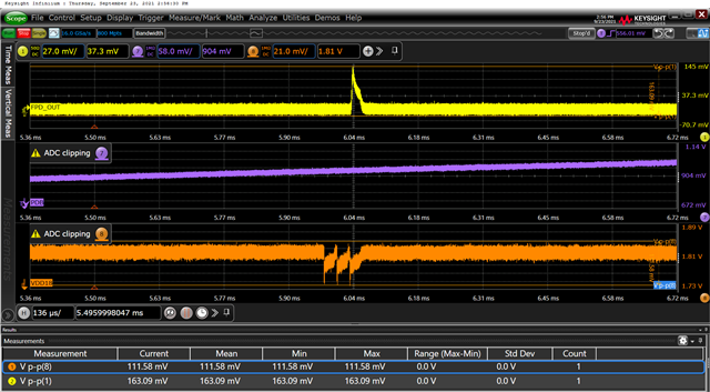
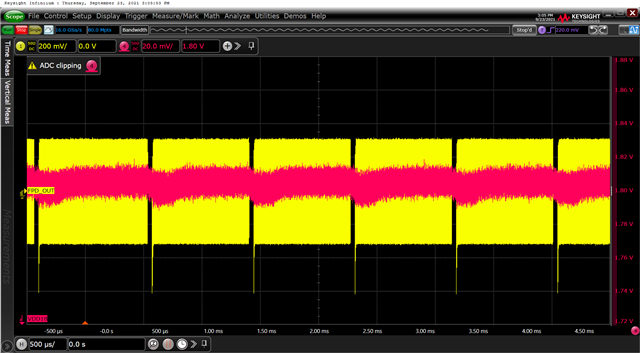
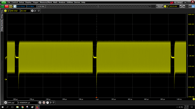
In the same configuration as pictured above (i.e. SER terminated into scope) I notice that every ~1ms, the serializer goes to electrical idle.  There is an RC time constant before the signal is back to nominal levels.  Is there a way to force continuous output and avoid electrical idle?

Where do I connect the 81160A on the SER EVM to perform the following test?  There is no connector on the board where TP1 is screen printed.

thank you!

-Kevin Kershner

  • Hello Kevin,

    You should not be seeing the FPD-Link forward channel drop out like that. Are you able to provide a scope capture of your power sequence and also verify there isn't excessive noise on the power pins?  A register dump would be useful as well here.

    Regards,

    Nick

  • Hi Nick,

    Thank you for the response.

    I am using a Keysight DC power supply connected by banana plugs to J19 (PoC Voltage) and J18 (GND).  I am supplying 12V DC, and the EVM is drawing ~50mA of current.

    I probed the supply pins with a voltage rail probe and measured ~7mV AC-RMS noise, and see no transients/anomalies on the line.

    I captured the register dump after power up and pasted below.  The forward channel signal behaves similarly to my previous screen capture upon power up:  it goes from electrical idle to transmitting, and then drops out at about 1ms.  Please let me know if you need something more specific than this.

    I would also welcome your comments on the other questions I posed in the first message.  thank you.

    -Kevin

    [REGISTERS]
    Device = ALP Nano 1 - DS90UB953, Connector 1
    Comments = ""
    Date = 08/09/2021
    Time = 09:39:10
    Reg = 0,0x0000,0x30
    Reg = 0,0x0001,0x00
    Reg = 0,0x0002,0x33
    Reg = 0,0x0003,0x48
    Reg = 0,0x0004,0x00
    Reg = 0,0x0005,0x03
    Reg = 0,0x0006,0x41
    Reg = 0,0x0007,0x28
    Reg = 0,0x0008,0xFE
    Reg = 0,0x0009,0x1E
    Reg = 0,0x000A,0x10
    Reg = 0,0x000B,0x7F
    Reg = 0,0x000C,0x7F
    Reg = 0,0x000D,0xF0
    Reg = 0,0x000E,0x0F
    Reg = 0,0x0010,0x00
    Reg = 0,0x0011,0x00
    Reg = 0,0x0013,0x00
    Reg = 0,0x0014,0x00
    Reg = 0,0x0015,0x20
    Reg = 0,0x0017,0x3C
    Reg = 0,0x0018,0x80
    Reg = 0,0x0019,0x62
    Reg = 0,0x001A,0x62
    Reg = 0,0x001B,0x62
    Reg = 0,0x001C,0x00
    Reg = 0,0x001D,0x00
    Reg = 0,0x001E,0x00
    Reg = 0,0x0020,0x00
    Reg = 0,0x0021,0x00
    Reg = 0,0x0022,0x00
    Reg = 0,0x0023,0x00
    Reg = 0,0x0024,0x00
    Reg = 0,0x0031,0x20
    Reg = 0,0x0032,0x49
    Reg = 0,0x0033,0x04
    Reg = 0,0x0035,0x00
    Reg = 0,0x0037,0x7A
    Reg = 0,0x0039,0x7A
    Reg = 0,0x003A,0x00
    Reg = 0,0x003B,0x00
    Reg = 0,0x003C,0x00
    Reg = 0,0x003D,0x00
    Reg = 0,0x003E,0x00
    Reg = 0,0x003F,0x00
    Reg = 0,0x0040,0x00
    Reg = 0,0x0041,0x7A
    Reg = 0,0x0042,0x00
    Reg = 0,0x0043,0x00
    Reg = 0,0x0044,0x00
    Reg = 0,0x0045,0x00
    Reg = 0,0x0046,0x00
    Reg = 0,0x0047,0x00
    Reg = 0,0x0048,0x00
    Reg = 0,0x0049,0x00
    Reg = 0,0x0050,0x20
    Reg = 0,0x0051,0xC0
    Reg = 0,0x0052,0x00
    Reg = 0,0x0053,0x00
    Reg = 0,0x0054,0x00
    Reg = 0,0x0055,0x00
    Reg = 0,0x0056,0x00
    Reg = 0,0x0057,0x00
    Reg = 0,0x0058,0x07
    Reg = 0,0x0059,0x07
    Reg = 0,0x005A,0x07
    Reg = 0,0x005C,0x00
    Reg = 0,0x005D,0x00
    Reg = 0,0x005E,0x00
    Reg = 0,0x005F,0x00
    Reg = 0,0x0060,0x00
    Reg = 0,0x0061,0x00
    Reg = 0,0x0062,0x00
    Reg = 0,0x0063,0x00
    Reg = 0,0x0064,0x00
    Reg = 0,0x00B0,0x04
    Reg = 0,0x00B1,0x4A
    Reg = 0,0x00B2,0x3F
    Reg = 0,0x00F0,0x5F
    Reg = 0,0x00F1,0x55
    Reg = 0,0x00F2,0x42
    Reg = 0,0x00F3,0x39
    Reg = 0,0x00F4,0x35
    Reg = 0,0x00F5,0x33

  • Hello,

    Thank you for sending the register set over, I will review.  To see the forward channel eye at 4.16Gbps you will need to set the device in non-sync mode and apply a 26MHz clock to the device.  Applying the external clock to the EVM may be difficult, I don't think there is a good point to connect a clock signal without soldering to the board.

    Regards,

    Nick

  • Thank you.  I look forward to hearing what you have to say about the registers.

    I would also like to point out that I plan to test the 954 EVM output (back channel) in a similar fashion.  Just FYI in case your input would be relevant to that setup too.

    Regarding clock input.  Can you make any recommendations, or provide examples (pictures, part numbers, etc.) of soldering a clock input to the EVM?  This would also allow me to test CTP 4.5a "Sink - Forward channel jitter compatibility to its link partner with reference cable"

    thanks,

    Kevin

  • Hi Kevin,

    I don't see anything that stands out in the register set I will have to see what else may cause intermittent dropout of the FPD-Link signal. It should be dropping the way it is in the scope capture you shared.  

    For the 954 there is already a 25MHz oscillator on the board so you can use it the way it is and try to read the eye directly.  If you want an adjustable clock input you could populate J21 and use a function generator to input a signal directly.

    As for getting an external clock to the device I think the easiest way would be to populate R1 and use the 50MHz oscillator already on the board. Set the device in external non-sync mode and look at the output eye.  

    Regards,

    Nick

  • Hi Nick,

    One thought I had about the signal dropout... 

    I do not have anything connected to the J1 Daughter Card (i.e. no camera sensor).  Will this cause the output to behave like we are observing?  If I need a sensor, can you recommend a specific model to acquire?

    thanks,

    Kevin

  • Hi Kevin,

    Having an image sensor should not this effect on the FPD-Link communications.  Can you probe the power pins and the PDB pin and share a scope shot of the power-up sequence?  

    Regards,

    Nick

  • Here is the power rail in green.

    Can you please provide more detail where to probe PDB?  It is hard to tell from figure 5-2 of the SER Eval Module user guide.  thanks.

  • Hi Kevin,

    It may be difficult to probe on the EVM but you could try to probe R14, C21, or S1 on the board or the pin itself.  Also can you probe the VDD18 rail too?

    Regards,

    Nick

  • Hi Nick,

    I probed R14 and VDD1V8.

    (Please ignore the "ADC Clipping" message -- this is only there because the probes were detached from the pins when I took the screen shot)

    -Kevin

  • Hello Kevin,

    There definitely seems to be an issue with the PDB voltage.  Seems like the PDB voltage is spiking quite a bit which could cause the device to reset or not work properly.  VDD18 seems to have a ripple as well, how are you powering the board?  Can you try using the PoC network instead of local 12V?

    Regards,

    Nick

  • Hi Nick,

    The spike on PDB was my mistake - I made a bad ground connection on the probe.  This noise is gone now that I have grounded correctly.

    However, VDD18 behaves differently depending on the configuration.

    The ripple is NOT present when:

    1. SER is powered by PoC , FPD_OUT (J16) connected to DES, DES connected to 12V power supply at J1

    2: SER powered by 12V at J19, PoC enabled,  FPD_OUT connected to DES (DES J1 is disconnected)

    3. SER powered by 12V at J19, PoC disabled, FPD_OUT connected to DES (DES connected to external supply at J1)

    In other words, the ripple is not a function of where power is coming from, rather it is present when the SER is not connected to the DES.  

    How can I connect J16 to the oscilloscope and avoid the ripple on VDD18?

    thanks,

    Kevin

  • Hi Keven, 

    If this is a connection issue then I am not sure what how else to do it.  Let me see if there is a better explanation for why the device seems to idle like that momentarily.

    Regards,

    Nick

  • Hello Kevin,

    Sorry for the delays.  Were you able to find a way to get a better connection?  I don't know of a reason for this behavior other than a power issue or a PDB.  Is it possible to probe the pin directly?

    Regards,

    Nick

  • Hi Nick,

    Sorry for the delay.  I believe I probed PDB last time?

    Please provide me with detailed instructions of what you want to see, where to probe, and at what point of the startup I should trigger the capture.

    thanks

    Kevin

  • Kevin

      PDB is pin 8 of DS90UB953. The request is to probe right at Pin#8 of 953 and capture the transient behavior of PDB as it goes up

    Thanks

    Vijay

  • Thank you, Vijay.  I will be delayed by a week or so in taking new measurements.  I will update those findings here.

    Are you certain this ~1ms cyclical dropout is not related to the lack of a camera on the board? 

    I have used a different device exhibiting the same behavior.  When configured to serialize a CSI source but no camera is present, the same ~1ms dropout occurs.  However this device offers an alternative mode of operation where CSI is replaced by an FPGA pattern generator and the 953 does not exhibit the ~1ms dropout.

    In light of this information, I was hoping a configuration of jumpers and/or registers would achieve a similar result on the DS90UB953.  

    Or perhaps you could recommend a camera to attach to the DS90UB953?

    Thanks!

    Kevin

  • Hi Kevin,

    I don't believe this should be affected by the presence of an imager.  The FPD-Link communication should be present whether there is a sensor attached or not.  My concern is with the fact that it appears to drop periodically, which is why I wanted to verify no noise on the power pins and also the power-up sequence is correct.

    Let not add an imager until we figure out why we are having this issue first.

    Regards,

    Nick

  • Hello,

    I probed Pin8/PDB with a 500MHz passive probe.  Here is a 100ms capture at power-on, with no DES connected. 

    Please let me know if I should capture additional data.

    thanks,

    Kevin

  • This is on an EVM right? Can you get a capture of VDD18 and PDB on the same image?  I want to compare to mine?  Also using a differential probe with a max bandwidth of 200MHz can you capture VDD18 to see the noise?  I just want to compare to what I see on my EVM.

    Regards,

    Nick

  • All signals captured simultaneously:

    Close-up of the glitch event ~6ms after the trigger:

    Noise on VDD18 using differential probe with 1.8V DC offset:

    -Kevin

  • Hi Kevin,

    There definitely seems to be a dip in the VDD18 voltage that correlates with the signal being lost.  You were using a 953 EVM right?

    Regards,

    Nick

  • Yes it’s a 953 EVM. 

  • Okay I will try to measure on my EVM however to answer your initial question the forward channel lined rate is determined by the external oscillator you would be using in this scenario which would be 50Mbps which would give you 4Gbps.  If you want to use 4.16Gbps then you would need to swap out the 50Mbps oscillator with a 52Mbps oscillator.

    Regards,

    Nick

  • Hi Kevin,

    Can you try changing the mode of the device actually?  I am thinking there is a possibility that the forward channel is trying to lock onto some reflections possibly which is causing the PLL to unlock from the internal clock momentarily.  Can you change to Async mode by either setting the strap on the EVM (easiest way) or change register 0x03 after startup?

    Regards,

    Nick

  • Hi Nick,

    1. Placing a jumper across MODE (J8) has no effect on the signal, even after cycling power
    2. Changing register 0x03 (bit 4 =1; bit 1 =1) eliminates the dropout, however, the data rate decreases to only ~2Gbps.  This mode is labeled "CSI-2 Non-Synchronous CLK_IN mode (requires a local clock source)" .  Where is the clock actually coming from in this mode?  Is this why the data is only 2Gbps?

    Can you please confirm my settings for (1) and (2) above and let me know if there is something else I can change?

    thanks,

    Kevin

  • Hi Kevin,

    So in this mode the refclk will be coming from the external oscillator if it is available. I think you may need to populate R4 in order to get the full forward channel rate.  Also check the bits in register 0x05.

    Regards,

    Nick