This thread has been locked.

If you have a related question, please click the "Ask a related question" button in the top right corner. The newly created question will be automatically linked to this question.

TPD1E05U06-Q1: PIN LCR fluctuate range after ESD test(power down mode)

Part Number: TPD1E05U06-Q1

Dear team,

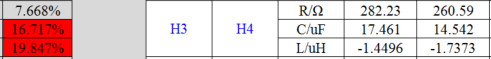
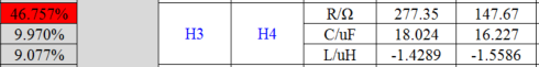
My customer uses this device for USB 2.0 interface. H3 and H4 are two USB pins. The CAR OEM has a requirement that they need to test LCR of USB signal pin before and after ESD test(power down mode), and then make sure the difference is smaller than 10%. But our device can't meet 10% requirement. I want to confirm with you whether 10% requirement is reasonable. Have we did such test? Do we have a range for LCD fluctuation?

Thanks & Best Regards,

Sherry

  • Hi Sherry,

    Can you clarify what the two tables are showing? The way I'm reading it, H3 and H4 are most likely the D+ and D- pins on the USB port, and your customer is comparing the LCR values of the D+ and D- lines on their board. The top table is the measurements before the ESD test ,and the bottom table is the measurements after the ESD test. I'm assuming both lines each have a TPD1E05U06-Q1 connected to them in parallel. Also, it seems your tables are only comparing the difference between the two lines twice. It's not measuring how the ESD test affected the lines.  Are my assumptions and interpretations correct? 

    If so, the TPD1E05U06-Q1 would not be causing this drastic of a shift. The only factor it would affect would be capacitance. Even then, this device's capacitance is only 0.42 pF, much lower than the uF values in the table. The shift is most likely caused by the board layout or something with the downstream circuitry like the USB transceiver or redriver. 

    As for the 10% LCR requirement, I'm not familiar with what a typical margin is since our devices don't affect inductance or resistance. This seems more like a board/system level test, not a device level test. 

    Regards,

    Matt Smith