


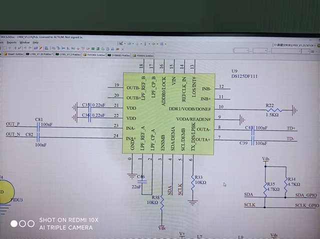
For some reason, when laying out the PCB,i need to set the input and output of DS125DF111 as shown in the figure, the input is OUT_P --- INA- \ OUT_N ----- INA+, and the output is also OUTA- ---- TD+ \OUTA+ ----- TD-, my question is, is it possible to reverse the input and output? Do you need to inverting the polarity in the configuration (0x1f 0f bit7)?
TKS!
Kevin
