


Part Number: TPS25750
Hello, by now I managed to fetch the PCB's and assemble the following circuit

As I said before I am trying to source 15V 3A from USB C using TPS25750.
I followed an earlier post here https://e2e.ti.com/support/interface-group/interface/f/interface-forum/988215/faq-tps25750-how-do-i-create-a-sink-only-usb-c-pd-port-to-replace-a-legacy-barrel-jack-connector and now I am not sure how to continue.
Here's my setup:
- I managed to pull the .bin file from ti's configuration tool and flash it to the EEPROM using raspberry pi. I picked the "Full flash" version and not the "Low addressing" option. I verified that my write was successful by reading the contents and comparing. The address of my EEPROM is 0x50 as per the datasheet requirements
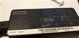
- I have two chargers wall adapters: one 5V 3A USB C dumb charger and one 65W adapter from lenovo (see photo)

- I attempted to use the setup in the post mentioned before which puts the chip in SafeMode (essentially grounding both ADC pins)
- I also attempted dividing the 3V3 voltage using 4 10k ohm resistors
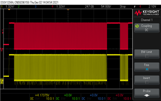
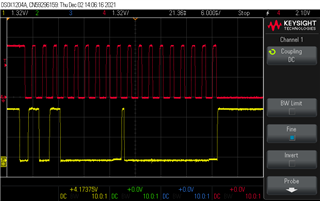
The result is the setup using the dumb 5V 3A input the device powers up and I get some i2c activity (see pictures). As you can see, in the second osci photo, the master writes to the EEPROM and the EEPROM gives an ACK which leads me to believe it has access to the flashed config.
However, with the 65W charger, it doesn't power up at all and probably doesn't load the EEPROM config.
Now I don't know if my above assumptions are wrong or I am not seeing something else that is obvious.
One of my issues in understanding is how to set the ADCx pins. I see the two diagrams below but I don't get how to divide the current so I am in the right "Mode".
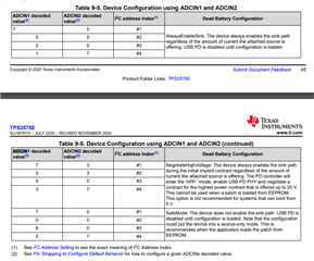
Also, what would be the "right" "Mode" for my case?
What I want to happen is:
Using the 65W adapter, power up in "Dumb 5V mode" so the EEPROM can load
Negotiate higher power and power up the PHV line
