


Part Number: TPS25750
Hi Team,
Our customer are evaluating TPS25750DRJKR at the following conditions.
Then, we have tree questions.
<Conditions>
-DRP (Source:12V/1.67A、9V/2.2A、5V/3A and Sink:8.4V/1.3A)
-Application have 2cell battery with BQ25792RQMR
-Configuration by external MCU (not EEPROM)
-ADCIN1 and ADCIN2 pins are GND
--------
[Q1]
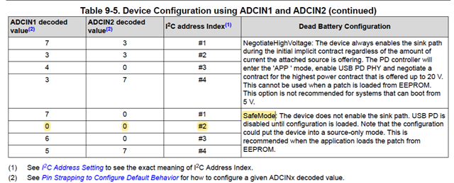
If configuration by external MCU (not EEPROM), could you please let us know the suitable setting of ADCIN1 and ADCIN2 pins?
Currently, TPS25750DRJKR is working fine.
However, we found other E2E thread.
According to this thread, “In order to enter AlwaysEnableSink mode, you will need to change the voltage divider on the PCB to set the ADCIN1 and ADCIN2 voltage to 1.5V.”
We understand that if ADCIN1 and ADCIN2=GND(Current our setting), TPS25750DRJKR is SafeMode.
Is there anything wrong with the different settings?
--------
[Q2]
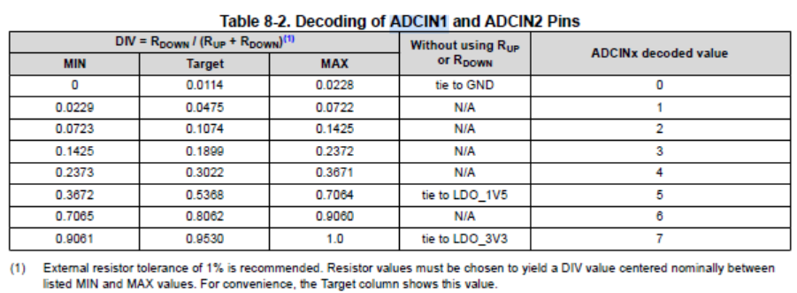
If your recommended setting are ADCIN1 and ADCIN2=1.5V,
We will connect ADCIN1 and ADCIN2 to 1V5_LDO pin of TPS25750DRJKR.
Is my understanding correct?
Other E2E thread
--------
[Q3]
I'm starting "configuration with the following steps.
However, in rare cases, TPS25750DRJKR cannot be started properly(I2C can’t communicate).
Step1: Power supply from Battery to TPS25750DRJKR
Step2: VBUS is connected to TPS25750DRJKR
Step3: Configuration from external MCU
Bye the way, if we tried the following steps, I2C can communicate always.
-Step1-> Step3-> Step2
-Step2-> Step1-> Step3
Could you please let us know this cause if you have any information?
I'm worried if ADCIN1 and ADCIN2 pin settings aren’t affecting TPS25750DRJKR.
--------
Regards,
Hide
