This thread has been locked.

If you have a related question, please click the "Ask a related question" button in the top right corner. The newly created question will be automatically linked to this question.

USB-PD-CHG-EVM-01: Can't work well

Part Number: USB-PD-CHG-EVM-01
Other Parts Discussed in Thread: TPS25750

Hi Team,

There is a Japanese customer who only has Gmail and can't post in our E2E, so I post here instead of him for help.
The customer now uses USB PD-CHAG-EVM-01 to evaluate USB PD, but it doesn't work well.
Although it is planned to implement patch bundle, it is not going well.
When purchasing USB-PD-CHG-EVM-01, it seems that it has been written into EEPROM, and 9V / 3A during operation is set to work as sink.
'BPMS' was sent to switch this, but an error occurred.
Because the mode is always APP, send "GO2P" first to switch the PTCH mode
This can also go error.

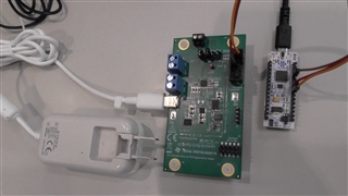
By the way, the customer uses USB-PD-CHG-EVM-01 to connect to the ARM board which is purchased in the market.
Run in the test program.

Do you need any pictures or screenshots to analyse this issue?
Hope to get your advice.

Thank you!

Regards,

  • Hello,

    Have you programmed the EEPROM at all since purchase? Can you please explain what about the PD contract is not working? What source/sink are you using with the board? Are you using a battery? Please give more specifics about the test setup.

    If you are having trouble flashing the EERPOM, please see the attached FAQ:

    https://e2e.ti.com/support/power-management-group/power-management/f/power-management-forum/1021134/faq-how-do-i-configure-the-tps25750-and-flash-the-eeprom-with-the-output-binary-for-the-board-usb-pd-chg-evm-01

    Thanks,

    Mike Emanuel

  • Hi Mike,

    Please find customer response as below.

    We have not programmed EEPROM since purchase.
    We are using a battery charger with the board.
    We don't have Aardvark and are not going to purchase it, either because we will not be able to apply TPS25750 to our product unless all controls are operated from MPU.
    So, we are now performing verification if this is feasible or not.
     
    Our test setup: MPU(ARM Cortex M4) is simply connected to J5 of USB-PD-CHG-EVM-01 via I2C. MPU is controlled by connecting with ICE.
     
    When a battery charger(the source) is connected, TP1(PPHV) turns 9V. 
    And when I2C communication is executed via MPU which is connected to J5 and registers are read, following values are shown:
     -EVENT1.PatchLoaded : 1
     -BOOT STATUS.PatchConfigSource : 5h
     -MODE: 'APP' 
    So, I believe that EEPROM does activate the operation.
    From this status, we are trying to load lowRegion.bin with Patch Bundle but we cannot switch APP mode to PTCH mode. This is troubling us.

    MPU is connected with J5 connector and I2C.

    Right after starting from EEPROM, we have APP mode. So we try to switch to PTCH mode using 'GO2P' before running 'BPMs' but the operation does not work correctly here.
    If we write a string 'GO2P' in CMD1 REGISTER and read DATA1 REGISTER, 3h is shown and not accepted.
    MODE REGISTER stays at APP mode and ReadyForPatch bit of EVENT1 REGISTER stays at 0 as well.
    Is it not enough to write 'GO2P' in the register to switch to PTCH mode?
    Would you kindly help advise us on the specific procedure to switch from APP mode to PTCH mode after starting from EEPROM?
    Thanks.

  • Hello,

    I still need more information about how you are connecting the board. What are your connecting on J1 and J2? What are your jumper settings? Are you aware that this board already has a battery charger on it? Why are you using another battery charger?

    The connector J5 is connected to the I2Cm lines, which is the line where the PD controller acts as a primary. You can only talk to the EEPROM and battery charger on this line. If you want to talk to the TPS25750 as a secondary you need to connect to J3.

    Thanks,

    Mike Emanuel

  • Hi Mike,

    I need to correct one point in my question.
    MPU is connected with J3 NOT J5.
    Apologize for my mistake.

    Currently J1 and J2 are not connected with anything yet but J2 will be connected with a Li-ion battery(2Cell) which is under procurement.
    USB-PD-CHG-EVM-01 will be used as a dedicated SINK and USB will be connected with following ones as examples:

    www.amazon.com/.../ref=sxin_12_pa_sp_search_thematic_sspa

    Using the above-mentioned charger connected with USB, we are considering charging the Li-ion battery which is connected with J2.
    We haven't investigated the charging function of BQ yet and are studying USB PD controllers before that.

    Please let us know if you need further information.

    Additional question:
    The FAQ you provided about Aardvark says that Aardvark shall be connected with J5 to write dullFlash.bin. Would it also be possible to write it with 4CC from I2C(Slave) of J3?
    I was assuming that we can write EEPROM by sending fullFlash.bin using 'BPMs.' But is this my misunderstanding?

  • Hello,

    Please clarify what you mean by 'BPMs?'

    Yes it is possible to program the EEPROM by talking through the TPS25750, but the process is more complicated because of the 4CC structure. It would be easiest to flash the EEPROM directly by connecting to it directly.

    Can you please share some more information about the specifications of your adapter? I see that it is a 20 W adapter, I would like to know what voltages and currents it offers. I suspect because it is 20 W it only supports 5 V and 9 V. Please confirm if I am wrong or not. The default flash has it configured with 100 W capability, but you cannot realize the higher voltages/currents if your adapter does not support certain voltages.

    Thanks,

    Mike Emanuel

    Please click "Resolved" if this answered your question.

  • Hi Mike,

    Followings are the specs of adaptors we are using:
     5V 3A
     7V 3A
     9V 3A
     12V 2.25A
    I think our adaptors are UAB PD V2.0 and older versions.
    They are mobile phone accessory adaptors and not for sale.
    We are also procuring a charger which can support 60W to 100W.

    What we are currently trying to do with 'BPMs' is to switch APP mode of TPS25750 configured in EEPROM to PTCH mode and operate it by loading a differently set-up lowRegion.bin.
    We will perform tests not by writing EEPROM each time, but instead by switching the configuration with lowRegion.bin.
    Let me go back to the main point. After starting from EEPROM, before loading lowRegion.bin using 'BPMs,' I assumed that we need to switch to PTCH mode by 'GO2P.' Is this correct?
    We also tried to run 'GO2P' in order to switch to PTCH mode but the Task was rejected.
    How can we resolve this situation?

    Note: in the future, we are planning to use I2C to write EEPROM.
    It sure is easier to directly write I2Cm and we can use that process for our tests but we will not be able to adopt the procedure in our actual products.
    I understand that the process is more complicated if we want to program EEPROM by talking through the TPS25750, but we still want to realize flashing from I2C.
    If any detailed materials explaing that procedure are available, would you kindly provide them or share us the link to such materials?

    Thanks.

  • Hi Frank,

    Let me look into this request and I will get back to you shortly

  • HI mike, Adam,

    Is there any update on this issue?

    But when customer is looking for the E2E forum, there was the same contribution as the content troubled by another problem although it is different from the GO2P that corresponds to the present,
    e2e.ti.com/.../tps25750-tps25750-i2cr-task

    As for the post I2Cr / I2Cw of 4CC,
    Is this unresolved at present?

    I used I2Cr and tried to read the BQ register.
    I was troubled with the same symptom as the above mentioned post content.
    If it was resolved,
    Please tell me the details.
    If you are unresolved, we will look at this post.

    Thanks.

  • Hi Frank, 

    This was Chuck's response to the post you linked:

    A release will be published later this week to address this issue.  Please check back starting on Wednesday and look for version 7.02 of the GUI that will have a patch in place for this issue.

  • Hi Adam,

    For i2cr, we confirmed the operation at TPS25750 application customization tool v7.02.
    Although it is the subject GO2P, I tried to solve at v7.02, but the situation is not changed and it does not become PTCH mode.
    What is the current situation?
    When can I get the answer?

    Thanks.

  • Hi Frank,

    Can you send me an I2C capture for the I2Cs bus on the EVM board?

    You will need to remove the EEPROM from your board so that we can work through getting the TPS25750D to boot from your connected MCU.

    We support 2 different configuration options:

    1.  EEPROM Boot (This is the mode supported by the USB-PD-CHG-EVM-01)

    2.  AlwaysEnableSink This mode allows you to boot from a connected MCU because it will enable to powerpath at 5V without communicating with the EEPROM. 

    In order to enter AlwaysEnableSink mode, you will need to change the voltage divider on the PCB  to set the ADCIN1 and ADCIN2 voltage to 1.5V.  

    Once you have done this, then you should be able to follow the instructions for the PBM flow to work as documented.

  • Hi Chuck,

    Please see the following I2C packet capture when GO2P is executed. 


    // Read BOOT STATUS
    SDA : 422D
    SDA : 43051C00F2A2A1

    // Read EVENT1
    SDA : 4214
    SDA : 430B0810204500000000000001

    // Read MODE
    SDA : 4203
    SDA : 430441505020 // 'APP '

    // Write DATA1 (Zero Clear)
    SDA : 42094000000000000000000000000000000000000000000000000000000000000000000000000000000000000000000000000000000000000000000000000000000000

    // Write CMD1 'GO2P'
    SDA : 420804474F3250

    // Read CMD1
    SDA : 4208
    SDA : 430400000000

    // Read DATA1 (Reject task)
    SDA : 4209
    SDA :  434003000000000000000000000000000000000000000000000000000000000000000000000000000000000000000000000000000000000000000000000000000000

    // Read MODE1
    SDA : 4203
    SDA : 430441505020 // 'APP '


    If EEPROM is removed, it will turn to PTCH mode right after booting. This does not follow the intention of my question.
    Do you mean that after TPS25750 is configured with EEPROM, a mode change from APP mode to PTCH mode cannot be executed even when GO2P is used?

    >In order to enter AlwaysEnableSink mode, you will need to change the voltage divider on the PCB  to set the ADCIN1 and ADCIN2 voltage to 1.5V.  

    But LDO_1V5 is directly entered for the mode supported by the USB-PD-CHG-EVM-01.
    Should AlwaysEnableSink be adopted even to this type of circuit?
    And if ADCIN1/2 are connected to GND, AlwaysEnableSink will not be applied?

    Thanks.

  • Frank,

    Let's take a step back and make sure that I understand how you are wanting to use the TPS25750.

    There are 2 methods for configuring the TPS25750D.

    1.  Booting from a programmed EEPROM.  This is the mode that is implemented on the USB-PD-CHG-EVM-01.  You will need to program the EERPOM according to the published documentation of the USB-PD-CHG-EVM-01.

    2.  Booting from a MCU.  For this mode to function, you need to follow the instructions above.

    Once I know where you are starting from, I can better guide you.

  • Hi Chuck,

    Thank you.

    Currenly we are testing the functions assuming that EEPROM is not implemented and configure PD controller from MCU.
    We will define what PD contoller can do & cannot do to judge the final product specifcation.
    After testing the functions and based on the test results, we will decide if EEPROM should be implemented or not.
    We have already confirmed configuration from MCU using BPMs / BPMc at a state where all range 0xFF is written in the EEPROM implemented in USB-PD-CHG-EVM-01 and configuration from MCU cannot be done.

    We are now re-testing BPMs at APP mode with the configuration done and checking if we can change to a configuration holding a diffrent content.
    We acturally tried to change from APP mdoe to PTCH mode using GO2P according to TPS25750TRM (sluvc05.pdf), but we keep receiving an error instead of a mode change at this moment.
    That's why I'm asking you this question.
     
    About ADCIN1/2, the engineer in charge of the circuit design has created prototype PCB in advance and so ADCIN1/2 is connected to GND.
    If 1.5V needs to be applied to ADCIN1/2 when booting from MCU as a mandatory condition, I need to sumbit a circuit desing change request to the engineer.
    For this time, since we are supposed to use the PCB as a SINK device, we should not use the SafeMode?
    Thanks.
    Regards,
  • Frank,

    The PCB will need to be configured so that the device enables the 5V power path to allow your MCU receive power and boot.  Once you have this functioning, you will be able to follow the procedure that you are already be following to configure the TPS25750D.

    Regaqrds,

    Chuck