This thread has been locked.

If you have a related question, please click the "Ask a related question" button in the top right corner. The newly created question will be automatically linked to this question.

TLK10031: 10G repeater application implementation

Part Number: TLK10031
Other Parts Discussed in Thread: TLK10232, TM4C129DNCPDT

Hi

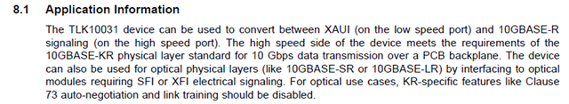
We are implementing 10G repeater application using 2 number of TLK10031 PHY transceivers.

Please find the attached block diagram for the application.

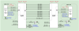
As per application we should connect HS to  TLK10031 High side (chip 1) , CHIP 1 it should convert to low  side of and to be connected to low side of TLK10031 chip 2 & from the HS of TLK10031 (chip 2) we shall receive the 10 G regenerated signal.

While testing, we are applying 10G signal from external source to TLK10031 High side (chip 1) but we are not getting any HS signal at chip 2.

While testing we have checked the values of following pins.

PDTRXA_N (Pin A8) : HIGH

PRBSEN (Pin B9) : HIGH

ST, MODE_SEL (Pin M9, H10) : LOW, LOW as per mentioned in datasheet.

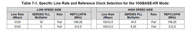
We are providing input clock : 156.25Mhz

But we are not able get the output.

LOS_A (Pin E9) , PBRS_PASS (PIn J9) are continously low.

Please support us

  • Hi,

    Some debug tips below.

    • Make sure TESTEN is grounded
    • Please ensure SerDes multiplier settings for 10G KR with 156.25MHz clock are being applied.
    • Make sure you are implementing TLK register settings for 10G KR with link training case. You may refer to the example settings per embedded file below

    E2E_KR_Case_cfg.xlsx

    Thanks,

    Rodrigo Natal

  • Thank You Rodrigo Natal for fast response,

    TESTEN is grounded and the system clock is 156.25MHz. 

    We have not yet started with software development. So we are not able read or write the TLK registers for time being. We want to check that TLK will work in default register values or not.

    I need one clarification i.e. Can we implement loopback with default registers values of TLK(without altering register values)?

    Thank you in advance.

  • The TLK serdes should default to 10G Ethernet KR mode. I don't think you can enable loopback without register writes. You may instead try implementing loopback externally via your system electrical connections.

    Regards,

    Rodrigo Natal

  • Thanks again Rodrigo Natal for your response,

    So as per your thoughts i think I will consider register writes are necessary for implementing loopback.

    And can you elaborate what is external loopback via system electrical connection? I didn't understand this.

    First we have implemented a direct loopback  with our 10G tester(Trex). Port 0 of tester is directly connected to Port 1 of tester. This connection is working fine. We are able see 10G data communication. And is this what your suggesting ur to do?

    But loopback is not working if we use TLK modules between these tester. 

    We have connected Port 0 of 10G tester(Trex) to Highside of TLK10031 module 1 and the High side of TLK10031 module 2 is connected back to Port 1 of our 10G tester. Low sides of both TLK's are connected as per the previous block diagram. This implementation is not working.

    So if you want us to write to TLK registers to make it work, if possible please tell us the procedure (like what all the registers we need to write). We have gone through the datasheet of TLK10031 but it didn't helped us.

    Note: Trex tester is used for generating 10G signal.

    Thank you.

  • Related to: And can you elaborate what is external loopback via system electrical connection? I didn't understand this.

    • I simply mean to physically connect the electrical outputs for a given TLK channel to the inputs of that same channel using connections at the system/board level

    The datasheet does list all of the registers and functions in gory detail. You may also leverage the TI software GUI to generate devices configurations.

    https://www.ti.com/lit/zip/sllc435

    https://www.ti.com/lit/pdf/sllu181

    Thanks,

    Rodrigo Natal

  • Thank you Rodrigo Natal,

    I downloaded and installed the TI software tool you have sent, but its not opening as I don't have National Instruments Labview Run time engine and the TLK10232 EVM to work with.

    Can you please tell me what all the registers to be updated to activate the link, because link is not establishing between 10G tester and TLK10031 when I connect the 10G optical cable between them. 

    And can you tell me what all the registers I need to update to enable basic working of TLK10031 module.

    Thank you.

  • Hi,

    This TI GUI should also work with TLK10031; TLK10232 is simply two- channel version of same device.

    I'm attaching for reference an Excel file containing reference settings to set TLK SerDes for 10G-KR.

    0552.E2E_KR_Case_cfg.xlsx

    Please note that, if you are using 10G optical interfaces, you would use the KR settings but you would need to disable link training and auto-negotiation.

    Thanks,

    Rodrigo Natal

  • Thank you Rodrigo Natal for the information,

    We are facing issue in reading/writing the registers only. We are not able to read/write the registers of TLK10031. We have tried a method using a reference document that we found from web. But still we are not able to read/write TLK registers using our controller(TM4C129DNCPDT). 

    Currently we are using Clause 22 frame format(MODE SEL pin is HIGH). Please can you provide any reference code for clause 22 or clause 45 read/write operation. 

    And we are using 10G SFP optical interface, can we use Clause 22 format for reading/writing TLK registers? Or is it compulsory to use Clause 45 format?

    Thank you.

  • Related to: "We are facing issue in reading/writing the registers only. We are not able to read/write the registers of TLK10031"

    • MDIO protocol is used to communicate to the TLK and perform register access operation. Do make use you have compliant MDIO/MDC signals and that the TLK MDIO address set via its PRTAD pins matches the address being applied at your system software level

    Thanks,

    Rodrigo Natal

  • Thank you Rodrigo Natal,

    Is PRTAD address required for Clause 22 format? I need some clarification regarding below data given in TLK datasheet.

    As per the above data, ne need of PRTAD address for Clause 22 format. Please help me understand this.

    And one more doubt is in clause 22 frame PHY ADD means is it PRTAD address or device address(like 0x1E for vendor specific registers or 0x01 for PMA/PMD control registers)??

    Thank you.

  • As per datasheet: "In Clause 45 (ST = 0) and Clause 22 (ST = 1), the top 4 control pins PRTAD[4:1] determine the device
    port address. In this mode, TLK10031 responds if the PHY address field on the MDIO protocol (PA[4:1]) matches PRTAD[4:1] pin value, and the PHY address field PA[0] = 0.

    Thanks,

    Rodrigo Natal