This thread has been locked.

If you have a related question, please click the "Ask a related question" button in the top right corner. The newly created question will be automatically linked to this question.

DS90UB929-Q1: How can I setting SSC to reduce EMI ?

Part Number: DS90UB929-Q1

Hello,

I found UB929-D/S can support SSC profile.

Can you explain how to setting the Frequency deviation and Modulation rate?

We would like using Spread Spectrum on LVDS signal.

But we didn't see any embedded register can do that.

What is the default SSC setting on UB929? 

For example: Frequency deviation: 2.5%, modulation rate: 50 kHz

Thank you.

BR.Doug 

  • Hello Doug,

    What deserializer do you plan to pair with 929? Also what HDMI source are you using which supports HDMI SSC? This is very uncommon 

    Best Regards,

    casey 

  • Hello Casey:

    We are use 924 to pair with 929.
    Normally our display was show color bar pattern come from 929 pattern generator not HDMI source.

    Does it SSC setting only for HDMI input source? or is there have possible to change output CLK on LVDS signal when we used 929.

    Our main purpose is improve 76MHz~108MHz of radiated emission (RE) test. 

    Thank you.  

    BR.Doug

  • Hello Doug,

    If you want to use SSC, then the HDMI source would need to be able to provide an SSC clock+data to the 929. These parts do not have internal SSC clock generation. So this is why I ask what source you are using and if it can actually generate SSC output. 

    With proper shielding of the systems and high quality cable the customer should be able to meet EMC requirements without needing to use SSC. Can you share what specific EMC test you are doing and also info on the setup? Pictures?

    Best Regards,

    Casey 

  • Hello Casey:

    I got it.

    Due to structure design, our enclosure material is plastic and we already used shielding cover on all chip.

    We just focus on radio frequency radiated emission test.
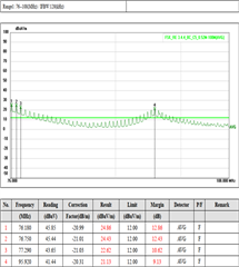
    Test results as below: 76MHz~108MHz (Average)

    The customer spec is more strict than CISPR25 level 5.

    Later I will info you setup environment of lab.

    BR.Doug

  • Hello Doug,

    What kind of cable is being used here and where is the noise getting measured? Also what is the PCLK rate here for the video?

    Best Regards,

    Casey 

  • Hello Casey:

    We used HSD@+8 cable with copper braid sleeve and noise is come from display side.

    The PCLK rate setting is 48.21MHz, it's depending on resolution 1920x360.

    BR.Doug

  • Hello Doug,

    How has the noise been isolated to the FPD-Link devices specifically and how are the display side signals being shielded? 

    Best Regards,

    Casey 

  • Hello Casey:

    We are try to separate the FPD-link device and display side, when we removed display it can found noise were be improvement so much. 

    And we also request display all chip have shielding cover. 

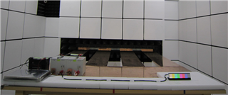
    Here we attached the test setup environment.

    The image source through by FPD-link cable between 929-EVM and DUT.

    BR.Doug

  • Hello Doug,

    Please allow me a little bit of time to look at this and provide some suggestions. I will respond back tomorrow 

    Best Regards,

    Casey 

  • Hello Doug,

    I'm still not sure how the noise has been isolated to the FPD specifically, especially since the frequency that you are seeing issues at does not seem to directly correlate with anything specific in the FPD parts. Can you try turning off the screen backlight only to see if the issue goes away? Another experiment could be to turn off the TCON for the display while leaving the FPD path running 

    Best Regards,

    Casey

  • Hello Casey:

    Sorry, reply to late.

    We still need booking 3rd party lab to check that. If any, we will update to you soon.

    Thank you.

    BR.Doug